Design Of Strong, Stiff, And Light Structures And Joints
The most common barrier between your team and your performance goals is reliability. These design best practices are intended to help you create strong, stiff, and light mechanical designs. Every design requires tradeoffs, and this list is not intended to be a set of absolute rules; but it will help you identify common design strategies to follow, pitfalls to avoid, and will inform your design decision making.
1. Use the engineering design process. The most common mistake is to only get a general idea of your objective and then to begin creating a solid model and performing stress analysis on the first idea you have. You will miss out on developing a much better solution and will often spend much more time iterating in the detailed design phase than you gained from skipping the first two phases.
Articles Tagged Project Management / Systems V
There are many different formulations of the design process. I roughly separated it into 4 phases.
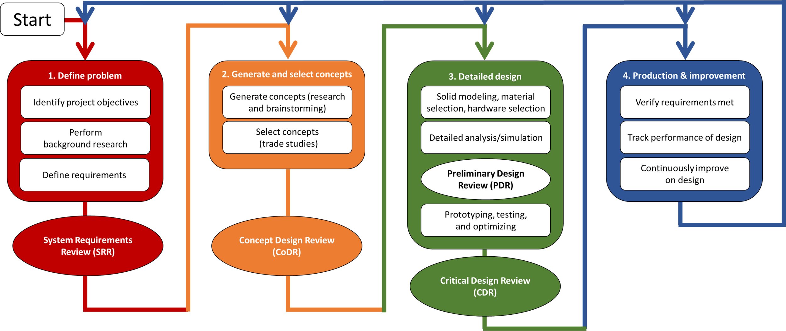
1a. First phase: Your team will fully define the problem through identifying your objectives, performing background research (back-of-the-envelope calculations, getting input from experts and users, etc.), and will culminate in the generation of measurable requirements that your design needs to achieve to meet your objectives. Requirements can be tiered from high-level (overall system) to low-level (subsystems). The requirements can be used when selecting the design concept in second phase and they will be verified in the fourth phase. Each of the first three phases can have reviews to ensure your team has done a thorough job in that phase.
1b. Second phase: Your team will generate as many concepts as you can through brainstorming, researching past designs, designs from other organizations, receiving input from experts and users, etc. If you can identify the strengths and weaknesses of your design concepts and designs from others you can then strategize how to maintain the strengths and improve the weaknesses of the design concepts to result in an approved design. A design concept is typically selected through quantifying trade studies (sometimes called decision matrices).
1c. Third phase: Your team will create solid models, detailed drawings, perform analysis and simulation, and prototype and test. It is not uncommon to use less refined prototypes in earlier phases. During this phase you want to leverage the power of combining theoretical analysis, computational analysis (simulations), and testing to give you the highest possible confidence your design will meet your requirements using the least amount of time and resources.
1d. Fourth phase: Your team will produce your design, verify it meets your requirements, test and track the performance, and then return to any of the phases to improve your design. Your design can always be improved, and iteration is an effective way to steadily improve your design. Ideally you are steadily simplifying your design as your design is done when you cannot take anything away from it — see next item.
2. Keep designs as simple as possible; This involves the strategies below. There will always be tradeoffs during these decisions, and you should use your requirements to drive the decision making.
2a. Minimize number of parts.
2b. Minimize the number of fasteners.
2c. Minimize the number of machined surfaces.
2d. Keep parts symmetric when possible.
2e. Use or modify parts that can be purchased.
2f. The best part is a part that is not there. It takes zero time to make, costs $0, and will never break. If you do not need it, it shouldn’t be a part of your design.
3. Consider how you are loading your designs – avoid putting components in bending.
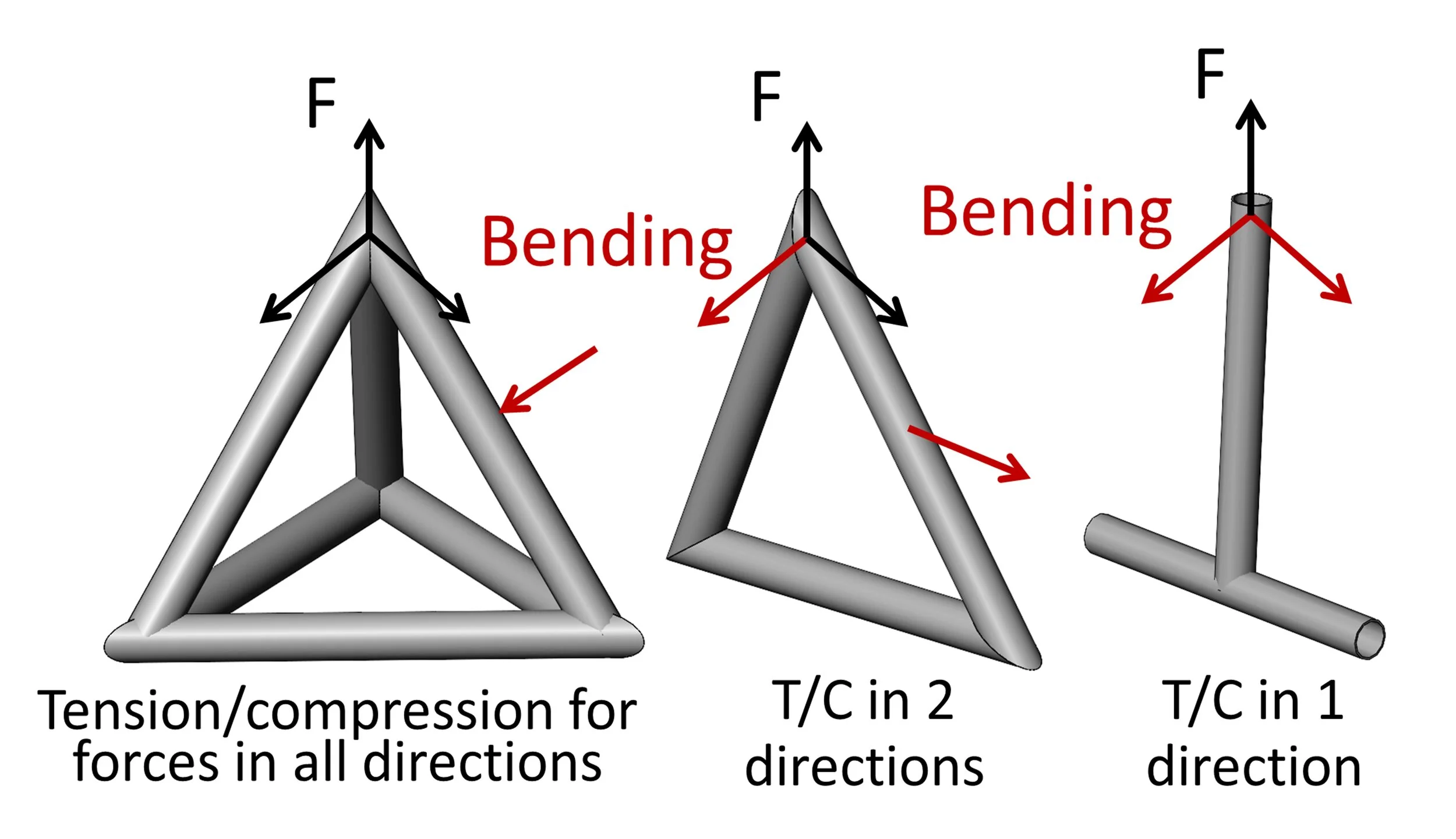
3a. Put material in compression, tension, or shear (double shear when you can) as this fully uses the entire cross section of material to hold forces and will result in strong and stiff structures. In bending, the material near the centerline is not used and the force applied is amplified on slender members due to the length being significantly larger than the thickness of the material. Move material to the top and bottom of the part if you must have bending (I-beam and square tubing are good examples of cross sections that do this). You should also avoid putting parts in torsion when possible, because the center of the material not used. If you need to put material in torsion, like axles for example, use a tube when possible to maximize the material at the outer edge.

3b. Use tetrahedral and triangular shapes with loads at the nodes of the shapes to keep material in tension and compression and to keep them from being in bending. Below I show an example using tubes, but this principle can also be applied to small parts. You will find that when you perform topology optimization it will result in parts with tetrahedral and triangular geometries.
3c. Design for your system to break in a way that is safe and easy to fix if your system is exposed to abnormally high forces.
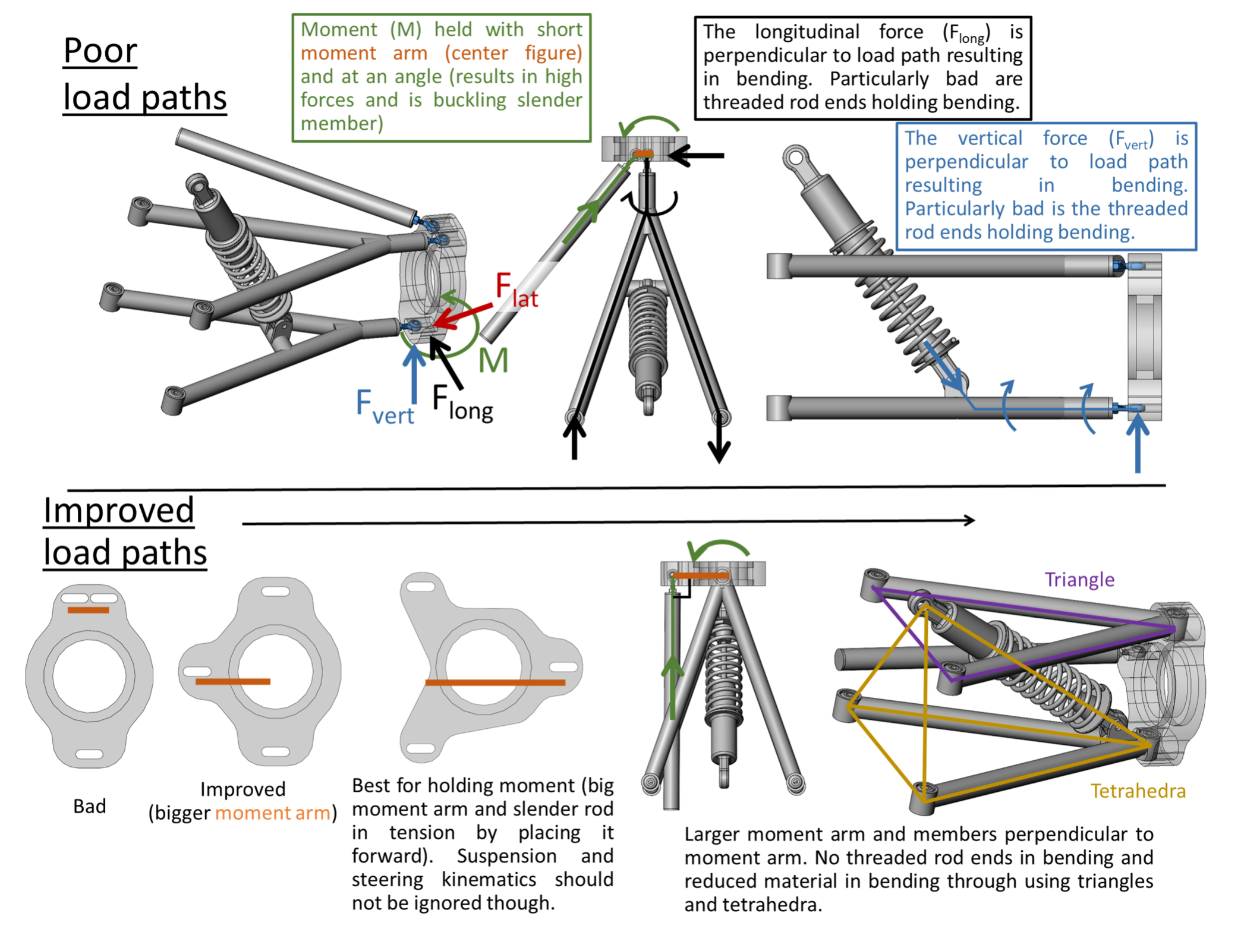
4. Consider load paths in your design. Strong and stiff designs with little mass require careful consideration of the loads you are holding. The top suspension holds the moment (green) with a short moment arm (orange) and with a two-force member at an angle away from perpendicular to the moment arm; this will result in high forces and will place this slender member in buckling. The longitudinal (black) and vertical (blue) forces are placing the threaded portion of a rod end (thread with spherical bearing at the end) in bending. This can be identified by the force being perpendicular to the load path.
A few ideas to improve the design are shown below, which include switching rod ends for spherical bearings (swivel joints) housed in the tubing and moving the mounting points further away from each other. The design is further improved through moving to a triangular A-arm—instead of Y-shaped—and through mounting the shock, pushrod, or pullrod to point at either of the spherical bearings—effectively making your design a system of tetrahedra and triangles.
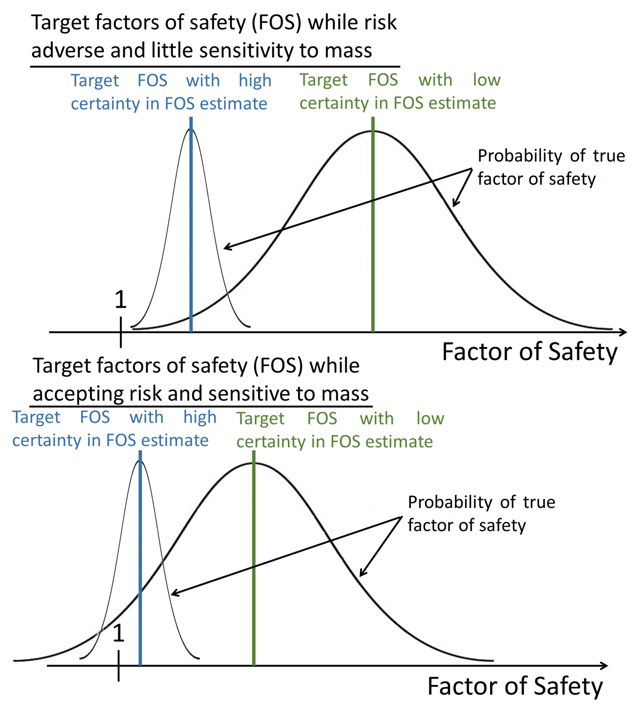
5. Your choice of a target factor of safety (FOS) should include how certain you are in your estimate of the FOS, how much risk of failure you can accept, and how critical the mass of your components is to your objectives. To have the highest certainty in your estimate of the FOS you need to understand the loading cases for your design and combine your computational results with testing and theoretical analysis. Fatigue analysis should be done for parts experiencing cyclic loading, especially for non-ferrous materials that do not have endurance limits—ferrous materials typically have endurance limits near half of their ultimate strength. If you have a high certainty in your estimate of the FOS, if you can accept a higher likelihood of failure, and if mass is not significantly restricted, then you can use a lower FOS.
You should not move onto the next step in the design process when you find the minimum FOS of your design is above your target—or below it for that matter. You should attempt to lower your FOS to your target and to have that FOS throughout your part if you want your design to be as light as possible. You can perform topology optimization, but you can also find where there is little stress in your part and remove material in those locations and add material to hold the loads in tension, compression, and shear where needed and reanalyze your design. As a quick reference, unmanned space applications can have FOS of as low as ~1.1 for yielding and ~1.5 for failure (ultimate strength) as they are highly sensitive to the mass of their designs and they complete extensive testing, analysis, and simulation; ground systems and vehicles frequently have factors of safety in the range of 2-5; and safety equipment can have factors of safety as high as 15. You will have to use your own judgement and your organization’s standards to determine the best targets for your designs.
6. The design of a bolted joint can include stress analysis of the fastener and joined material, joint stiffness, joint friction, bolt grip length, bolt torque specification (proof strength is important here), and whether to use positive locking features (locking nuts, safety wire, …). The FSAE series resources has an amazing resource here from Michael Black called Threaded Fasteners for FSAE. Here I will mention a few best practices and common mistakes to avoid to help with creating strong and stiff joints.
6a. Do not use bolt heads to hold a moment. Forces perpendicular to the axis of bolts should go through the center or be in line with the bolt pattern when possible. Note: In the lower row of the figure I only show the perpendicular component of the force being applied for simplicity.

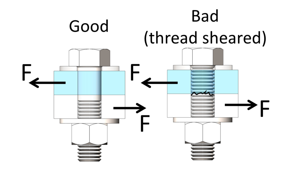
6b. Do not use threaded portion of bolts to hold shear; The shank of the bolt should extend beyond the shear plane. If you are not using friction between the plates, you might consider using a pin instead.
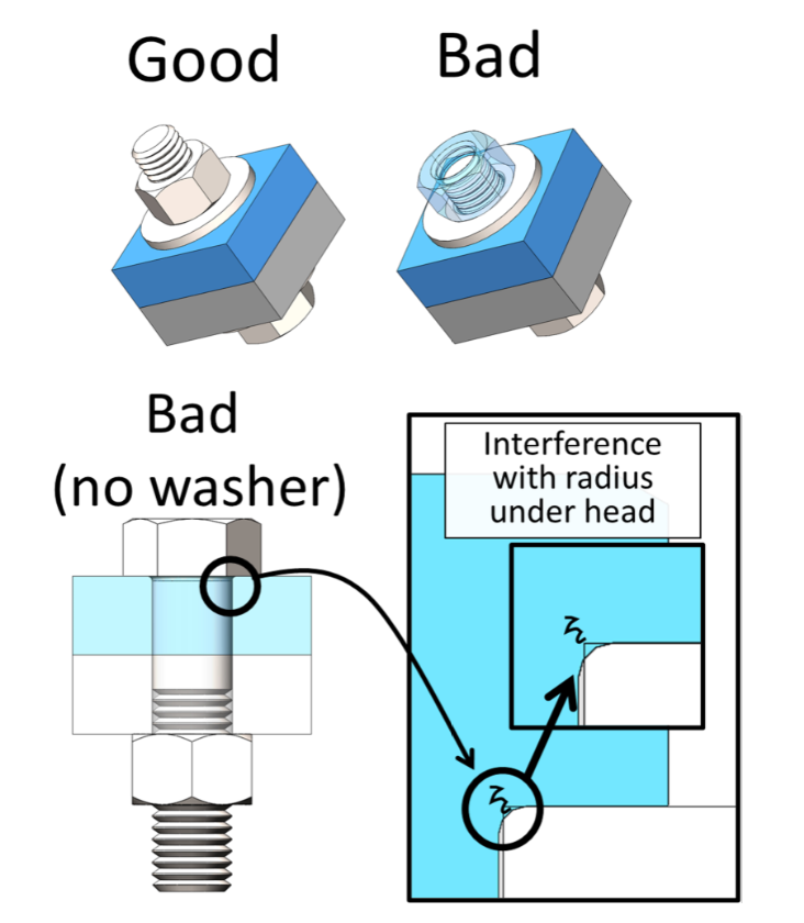
6c. Make sure a bolt has at least 3 threads extending out from the back of nuts as the first threads on a bolt do not have the full major diameter. If you cut the thread off, than it can be flush. Use washers under the head of bolts and under nuts. They will reduce wear and stress concentrations, especially at the radius between the head and shank of fasteners.
6d. When designing a tapped hole, a bolt needs to typically engage with a length that is at least ~1x diameter of the thread when using the same material. For a hard bolt in soft material, such as steel in aluminum, at least 2x the major diameter is advised or using a threaded insert like a Keensert is often used in critical applications. It is best to analyze the factor of safety and test the joint strength.

7. Avoid sharp changes in shape as they will create stress concentrations that will be more likely to fail – especially from fatigue loadings.

8. Do not place holes near edge of material. Keep hole edge >1.5 x the diameter of the hole and >3 thickness from the edge, as a rule of thumb. It is best to analyze the joint for tear-out if the plate is holding shear forces.

9. Use exactly constrained designs to avoid assembly stresses. Do not over-constrain your design.
9a. Do not use multiple fasteners going through tight clearance holes or multiple countersunk fasteners. Use one tight clearance hole or registering feature with a slot or loose clearance holes when you can.

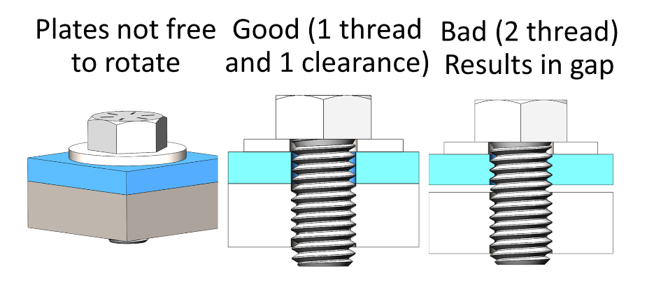
9b. Do not use two tapped holes for one bolt in parts that are not free to rotate; they will result in a gap during assembly even when fully tightened.
9c. Do not use four legs on a surface when you can use three. Three legs will not rock on an uneven surface.

9d. Do not hold a shaft with 3 bearings when you can use two.

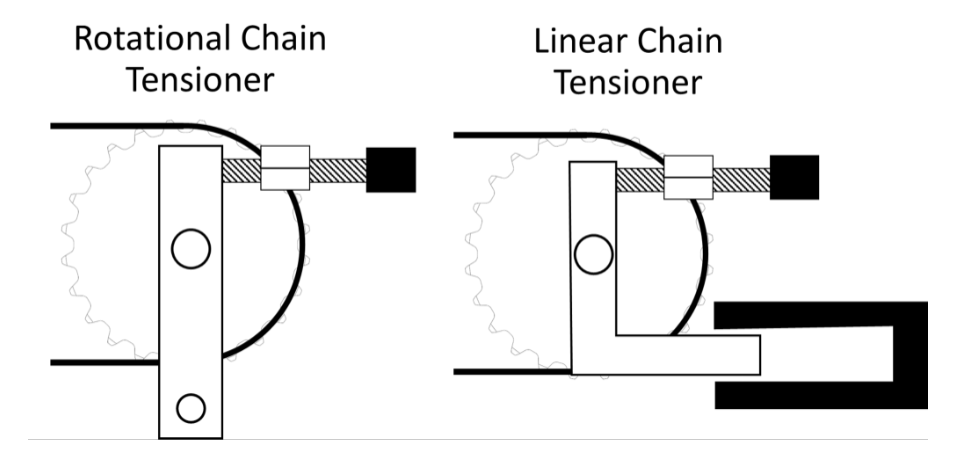
10. Use rotary motion over linear motion when possible. Example below shows a rotational and linear chain tensioner. The linear system is going to be harder to design and build to work well for a long period of time.
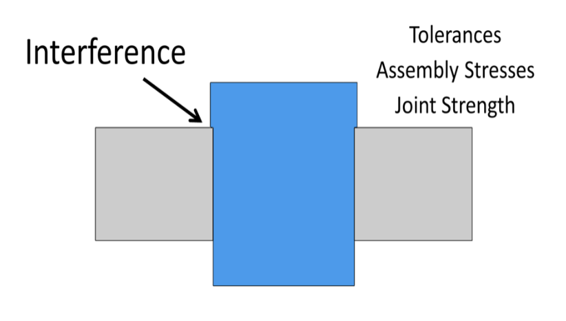
11. Avoid interference fits when possible, as they require careful design and tight tolerances. You will need to consider the tolerancing of the parts and the resulting range in potential stresses and joint strengths.
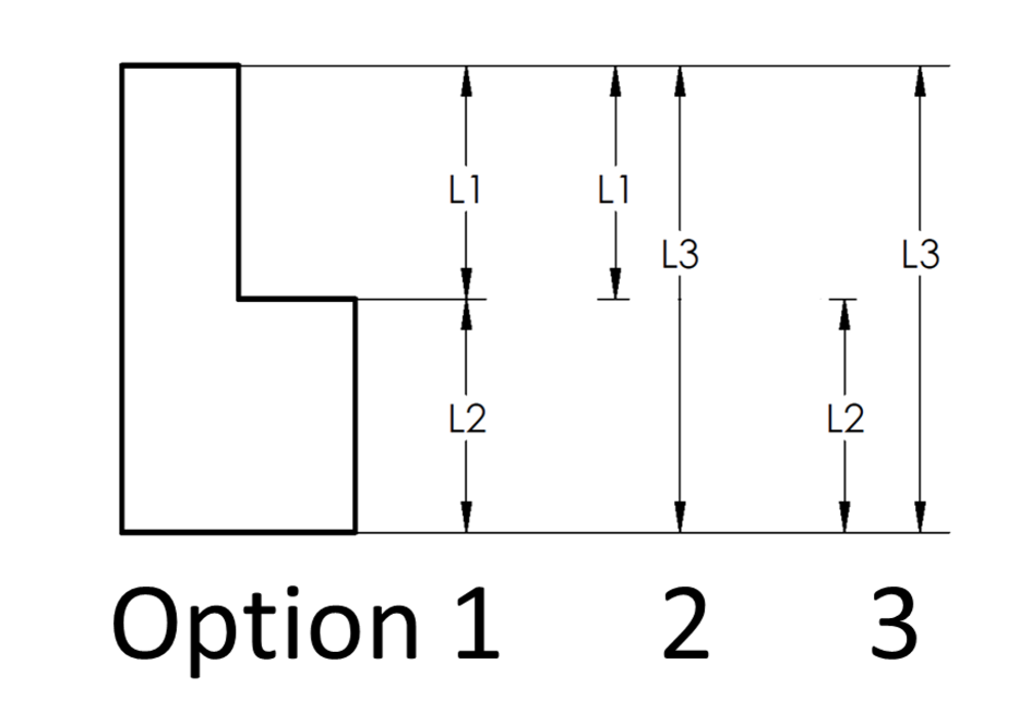
12. Design and tolerance based on function. In the example part below, there are three ways to dimension one side of it — and when using default tolerances, they will result in different tolerances for the part.
13. Design with manufacture and assembly in mind. Think about how you will make each feature you design. Think about how you will put together and take apart your design. Vehicles often require lots of disassembly and reassembly and you will thank yourself later if you only need a small number of tools (can do this through standardizing fasteners) and have designs that are easy to service by providing access to fasteners and having methods to remove components without removing several other components.
14. The best designers and those I learn the most from are very hands on. They — and you will too — learned to be a better designer by being involved in all parts of the design, build, and test process.
Chris Bachman teaches Mechanical Engineering at Cal State Los Angeles, and is the faculty advisor for the FSAE and Baja teams there.
https://www.calstatela.edu/faculty/john-chris-bachman-phd-pe