Dynamic Valve Event Optimization
Selecting Openings and Closings Even If Your Valves Won’t Totally Mind
The approach to understand what makes an engine run well is to look at the opening and closing of each valve.
But whatever you want the valves to do, they’re actually doing something else, because you always have:
Deflection (everything is a spring)
Inertia (it takes time for force to speed something up or slow it down, especially when its deflecting like a spring)
Vibration (when it springs back)
A lot of the differences in the data below may look tiny, but can have a significant effect
Think in terms of everything in a motor happening so fast, that in slow motion, what seems like a little vibration is a big wobble.
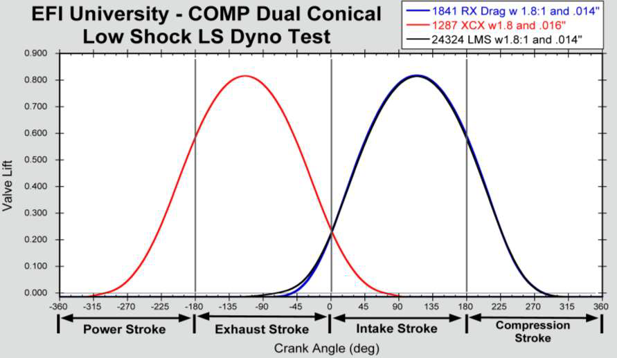
The black trace managed to control a valvetrain at a maximum speed 2000rpm higher than the blue trace.
This was originally presented at the 28th Advance Engineering Technology Conference, December 5th, 2017.

Looking at Valve Events, NOT Lobe Separation Angle (LSA) & Duration
You will hear many highly respected engine builders talking about Lobe Separation as if it was the most fundamentally important factor in selecting a camshaft, but it is the LEAST important by itself!
However, changing the LSA with the same two profiles is supremely important, as it changes all four valve events!
Can we think about timing events AND understand it only matters when they actually happen, not when we hope they happen?
The difference in theoretical and actual timing events is the primary weakness of most engine modeling programs.
What is a Cam Design? Cam Layout vs Valve Events


Advertised duration vs. duration at 0.075” valve lift
Considering and Moving Individual Valve Timing Points
Exhaust Opening
Overlap
Intake Closing
Exhaust Opening
On race cams this event occurs near the middle of the “Power Stroke”
Exhaust begins exiting the chamber and cylinder pressure drops rapidly
Some combustion is still occurring as the exhaust exits the chamber
Combustion pressure is now used to force out exhaust, not force down piston
The timing and speed of the exhaust valve opening point is key to the volume and tone of the exhaust note

There are all sorts of ways to measure the changes in the example above.
Exhaust cam duration = -4 degrees
Lobe separation angle = -1 degree
Advance = -1 degree
Exhaust Center = -2 degrees
None of those matter compared to the fact that:
Intake opening, Intake closing, and exhaust closing are exactly the same.
Exhaust opening is 4 degrees later.
On the exhaust, delaying the opening without reducing BDC lift can be significantly beneficial:
A longer power stroke without the pumping losses typically associated with a shorter exhaust duration
Overlap
During overlap both valves are open and this allows the intake and exhaust systems to link with one another and improve efficiency
Too much overlap reduces the vacuum signal and causes excessive misfire at idle, but some gives a nice sounding lope
The shape of the overlap can be more important than the duration or area
By tailoring the exhaust closing ramp and the intake opening ramp we can optimize this shape

Overlap at 0.000” Lift
Intake Closing
This is the most important valve timing event
When the intake valve closes, air stops flowing and pressure increases as the piston rises
This point generally determines the power range
Early intake closing tunes in the power earlier because it traps more air at low speed before it can turn around and exit back into the manifold
Later intake closings allow more air to enter at high RPM when the momentum of the intake charge allows filling even as the piston rises

So, How is a Profile Actually Developed?
Knowing that we are trying to get to certain events, we need series of lobes with identical opening and closing rates, symmetry, and dynamic behavior so that the Engine Builder can tailor events
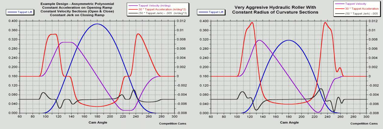
Good designs start at the valve or tappet motion with a more dynamic focus on Velocity, Acceleration and Jerk than the standard lift and duration
specs that are used by most selecting a camshaftLet’s look at these “Derivatives” of the motion and start talking about the foundation of Profile Development
Velocity
Velocity is rate of change in lift per camshaft degree.
The energy of the valve train system is proportional to the square of the velocity.
For a body with mass (m), and velocity (V), the translational kinetic energy, (E), is defined by E=1/2 mV^2.

Acceleration
Acceleration is rate of change in velocity per camshaft degree.
The forces acting on the valve train are proportional to the acceleration.

Jerk
Jerk is the rate of change in acceleration per camshaft degree.
The impact acting on the valve train system is proportional to the jerk.
It can also be understood as how quickly the forces are being applied and removed from the system.

How Does Camshaft Profile Design Play Back Into Valve Events?
We are always improving lobes to fit more area into a given duration window while still trying to maximize stability
On the intake, the biggest gains are normally found by increasing overall area and lift without increasing the duration
However, we do need to think about both deflection and stability (but that needs to wait a few slides….)
On the exhaust, delaying the opening without reducing BDC lift can be significantly beneficial:
A longer power stroke without the pumping losses typically associated with a shorter exhaust duration

Camshaft Profile Design Techniques
System Stiffness & Torsional Vibration
You knew there had to be a rub, right???
Every component has some compliance as forces are applied
The Rocker and Pushrod are the biggest factors but the Camshaft, Lifters, Rocker Mounting System and Valve all deflect under load
By measuring the deflection of the entire system loaded we can calculate the system stiffness and measure how individual changes affect the system as a whole without going to a dynamics test
Not only do the components deflect, but the cam rotation is not continuous due to both the drive compliance and firing pulses
System Stiffness (Lbs/Inch) = (Difference in Load)/(Difference in Lift )
The differences are between loaded load (LBS Spring Force of Real - Checking) divided by the change in lift with the checking and real spring.
The real spring puts force and deflection into the system. A checking spring (often used on flowbenches) is maybe a 1lb spring you can squish with your fingers.
If you had 500# open load on the real spring and virtually zero on the checking spring then measured .020” lift difference the stiffness would be 500/.02 = 25,000 lbs/inch
Note: With the same cam a less stiff system might make more power before it is optimized!
As Real Systems Have Non-Infinite Stiffness, The Compliance Changes the Valve Events
Every valve opening point will be delayed as the entire system “winds up” under initial motion and the closing points will be earlier (at
least the “first closing”) due to complianceAs general estimates:
Direct acting cam on bucket: 0.1mm
Finger follower system: Not much more
Rocker system, now you’re bending on each side: Up to 1mm
On every design, the positive acceleration sections (opening and closing) compress the pushrod (OHV) and bend the rocker arm
On the exhaust side, the initial compliance can be even greater as the valve has to open against the remaining cylinder pressure from
combustionOn Top Fuel Engines this delay can be dramatic

Note the max deformation was 20 degrees after Exhaust Opening on the lift error plot of this used Top Fuel camshaft

Blue is geometric design of valve movement, red is actual measured valve movement.

Practical Understanding Of Deflection
In the figure above, as rpm goes up, there is more deflection, which shrinks valve duration.
Always expect duration to drop off rapidly at some point (9500rpm in this case).
The forces get higher and higher, the deflection gets higher and higher (squared terms), and the inertial delay gets longer and longer.
The red line is a lighter spring. Less force to overcome, less deflection, better response and duration.
Computer Modeling of Valve Train
One of the primary reasons to upgrade our cam design software was to allow dynamic modeling
If we can run a virtual Spintron test of the system before making parts, it shortens the development cycle and helps us choose wiser time investments
Such software does little good without spending the time testing to ensure we have excellent model correlation

The black line is the intended geometry.The simulated red line, from left to right, show delay as the system winds up, pole vaulting off the surface, crashing back into the nose, bounces off again, then crashes and compresses on closing.
The black line is the intended geometry.
The simulated red line, from left to right, shows:
delay as the system winds up
pole vaulting off the surface
crashing back into the nose
bounces off again
then crashes and compresses on closing.

Strain gauge on a spring gives force. Force also gives spring position.

Every time you can take a measurement, you want to compare it to a model for validation.
A strain gauge on the pushrod shows excellent correlation to the model.
At 1000rpm, everything is normal and good.
At 8500rpm, there is a big hit, then it pole vaults off, crashes on the nose at maximum lift, bounces, and crashes on the closing.
Honestly the 500lbs after closing is an even bigger worry than the closing spike.

These laser measurements show really good valvetrain control. Pole vaulting over the nose starts at around 6500rpm, crashing on top of the nose is at its highest at 9000rpm, and the maximum lift is consistent from 9500 to 10750rpm.
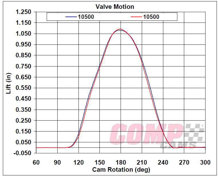
Same lobe, 60mm core (red) vs 70mm thick-wall core (blue) at 10500rpm. Even though they looked similar in the laser bounce graph above, the blue trace has a ton more area around a half inch of lift.
Maximizing Component Stiffness for Maximum System Stiffness
Whenever you are looking at any component between the camshaft and the valve, there are only three system attributes that effect engine
performance as follows
Stiffness
Mass
Durability

A Lesson From Competition Eliminator
For a while we have known a V8 could run a faster cam to the same RPM than an even fire V6 which can be faster than the odd fire.
Customers started to run flat crank I4’s that were literally just a COMP Eliminator V8 with a plate over one side.
Even with everything in the valvetrain identical, the I4 needed a MUCH smoother cam profile to run the same RPM without failure.
The Pro Stock Bike V-Twins were even less friendly…
We knew something had to be going on with torsional vibration but how could we get good numbers to this phenomenon?
Torsional Vibration
Not only do we have to deal with compliance of the valve, rocker, trunnion, stand, pushrod, lifter, cam and every bearing
We also have to deal with torsional vibration of the cam, drive system and impulses from the crankshaft.

To make any improvement, first you have to be able to take measurements.
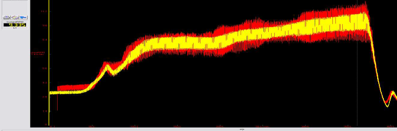
High speed 7200point encoder on the front of a Pro Stock camshaft.

First we have to make sure the data repeats.

At 10,000rpm the cam speeds up to 11,800rpm and slows down 8200rpm 10X PER ROTATION.
Try not to get sick to your stomach from the results.
Two full rotations of the crankshaft (above), 720 degrees, is one full rotation of the camshaft.
RPM are quoted as crankshaft RPM
Crankshafts do something similar from cylinders firing at different times.
Ruled this out: It did the same thing with the cylinders firing, as well as with no fuel and the crank driven at a steady speed.
Crankshafts whip (get twisted) due to rod forces
Did the math, forces on cams should lead to minimal torsional deflection
Ran sensors on both ends of the camshaft, doesn’t twist much (milliseconds or degrees)
This is just the result of forces to open and close the valves.
Forces are offset, slowing down the camshaft down while opening, going over the nose (centered), speeding the cam up while closing.
Sometimes, different valve events compound or cancel out depending on which side of the cam.
Remember the many-thousand pound forces from before.
That is enough to speed up or slow down the cam a lot.
Will stretch or deflect any belt, chain, or gear driving the camshaft.
Yellow: Pendulum camshaft damper added.

Yellow: Pendulum damper added, much better.
So, Why Haven’t We Seen Cam Dampeners Before?
They actually have been around longer than I have (literally).
First example I know of (but I bet there are earlier ones) is the 1968 Cosworth DFV with tuned torsion arms and a bronze dampener plate sandwiched in between sandwiched gears.
They hooked up alternators, water pumps, oil pumps, anything to load up the cam and even out the speed.
Later examples in F1 had pendulum or fluid dampeners
The problem with using these in most OHV applications is that reducing the torsional vibration will make the cam “act” up to ten degrees larger & reduce valve velocity, so the early dyno results will be a step back.
Previously, changes were selected based on the cam flying all over the place.
Making it stronger and stiffer, better control, you have to re-optimize to where valve events were happening before.
Relearning how to design a good cam will be hard!

Costowrth DFV Cam Plate Finger
Thinking About Flex and Twist
Having to deal with compliance and torsional vibration is NOT a no win situation with no way to make our lives easier!
Start at the VALVE
The lighter we are here the less spring is needed
ALL other components can be lighter with less total deflection
The less force slowing down and speeding up the camshaft.
Always try to run the lightest mass & load spring for an application
Run a complete System Stiffness check with ANY valvetrain change
Know that decreased deflection, reduced torsional vibration & lower loads ALWAYS increase the dynamic duration (mostly at lower lift)
Where are We Headed Next?
Once we realize there can be .050”+ deflection in the system before the valve even moves, how does that change the design approach?
COMP has developed several dozen new mini lobe series with different versions of a “Low Shock” or “Crack & Whack” ramp
We need to rethink where the closing ramp should be as well, and how to get out of the way underneath to keep from springing the valve open as the compliance is relieved
Low to Midrange Torque is not affected by .020” duration as previously believed (certainly not on the non-deflected opening side)