Background
Forum threads about Ackermann Steering:
Equivalent static toe?
Turn Centers
Max lateral acceleration
Peak Slip Angle at Peak Fy Characteristic
Not much said about changes in a car’s Understeer/Oversteer or Steering Gain throughout it’s range of Ay capability.
Introduction
Received a call from a FSAE student about a Cornering Compliances based simulation showing unexpected results when Ackermann steering was added to their Sim Handling Model. I studied this a long time ago (‘70s?), interested in the effect on tire wear. I was analyzing a huge amount of actual customer tire wear rates which included wheel alignments.
Dynamic Toe Change tests were organized to measure running toe under controlled conditions:
Constant speeds
Acceleration, Deceleration (coasting)
Braking
RWD Then FWD later.
The project begged for a simulation, so here it is (revised for the 21stCentury).
3DOF Parametric Model.
Nonlinear tires, steering, roll, plus anything else you want to add.
Spline, Pacejka5.2, PACE4(4 term Pacejka-Lite as in Bosch LapSim)
Built-in ISO test procedures.
Runs simplified vehicle models (7 Parameters) as well as with dozens of them.
Well documented correlation to road tests.
Approach
Start with typical sports or ‘Racecar’ Sim. Linear Vehicle, Non-Linear Tires.
Toe effects
Ackermann influences
Tire Model Flavors:
No Load Transfer Effects on Peak Tire Fy
Negative Load Transfer Properties on Peak Tire Fy
Positive Load Transfer Properties on Peak Tire Fy
Emphasis on Characteristics while Approaching Max Ay.
Define Concept in Easily Programmable Format
Matlab wrapper
WatcomFortran engine.
Create Tools for Simplifying & Exploiting
Tire constructor
Simulation Input and Output Preparation.
Limit Study to a Few Idealized Situations. If I was still working, road test results would accompany this discussion.
Mixed Ackermann Steering Definitions?
Arbitrary definition. (Literature?).
This Study:
Steer altered on inside AND outside front wheels in a turn.
Inside wheel is usual Reference.
Not a preference since outside wheel is usually dominant tire Force & Moment generator.
Simulation adds a “Dynamic Toe Element”:
Parabolic Function of Reference Steer Angle.
Both steered wheels are altered.
Sufficient Vehicle Sim Parameters
Mass: Front 930 kg, Rear 910 kg
Wheelbase: 2890 mm
Overall Steering Ratio: 15.5:1
Cornering Compliances installed via tire specs:
DF = 2.5 deg/g
DR = 1.5 deg/g
K = 1.0 deg/g (Linear range Understeer)
I know, you guys love those Neutral Steer cars, but not me …
Static Toe + 2ndOrder Ackermann Function
Roll Gradient: 3.5 deg/g
Pacejka-Lite Tire model:
User Adjustable Peak Force Slip Angle
50.5% FWD, 54 % Front TLLTD
Constant Speed, Ramp Steer
Test Speed: 100 kph
Useful Sim Features
Titles are Streamed with Sim Running Parameters:
Eliminates Interpretation Errors.
Benefit to Scatter-Plot Legends.
No Need to Manually Enter Run Details.
Easily modified and extra features, clarifications, labels, & metrics added as needed.
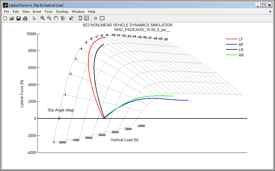
Tire Force & Moment trajectories on surface plots.

Entertainment Value: Show evolution of tire forces
The ‘Other’ Frequency Response
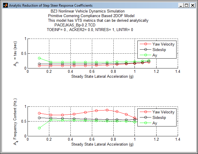

A1 = Steady State Amplitude
A2 = Decay Attenuation
A3 = Time Constant (1/Tau)
A4 = Frequency
A5 = Phase Shift
A6 = Drift Compensation (For divergent Responses)
t = time
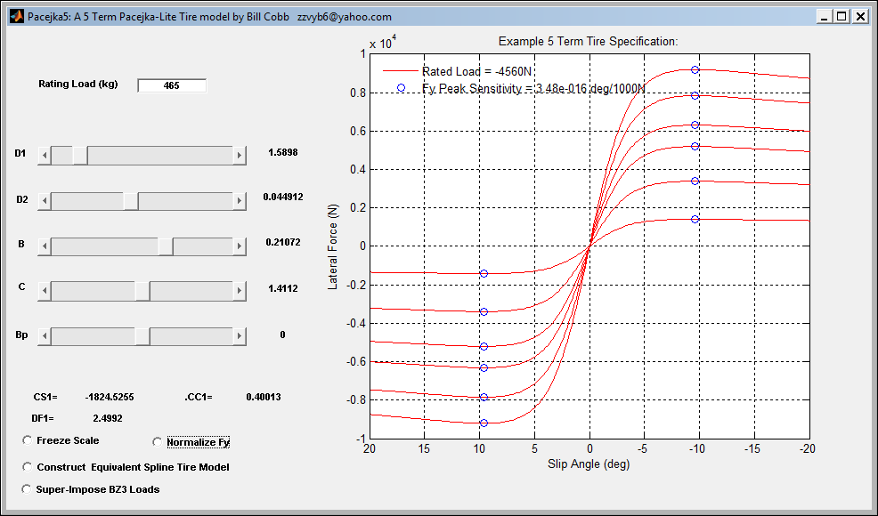
5 Term Pacejka-Lite Function
B, C, D1, D2, Bp
Bosch LapSim Model ( Bp == 0. )
Extra Parameter (Bp) to Designate Peak Fy Slip Angle
3 Tire Types Examined:
Peak Fy Slip Angle Advance with Load (Most common)
No Fy Slip Angle Advance with Load (Analytic models)
Peak Fy Slip Angle Reduction with Load (Camber influence)
Low Slip Angle Range Cornering Properties Preserved.
Peak Fy Slip Angle Advance With Load (Most Common)
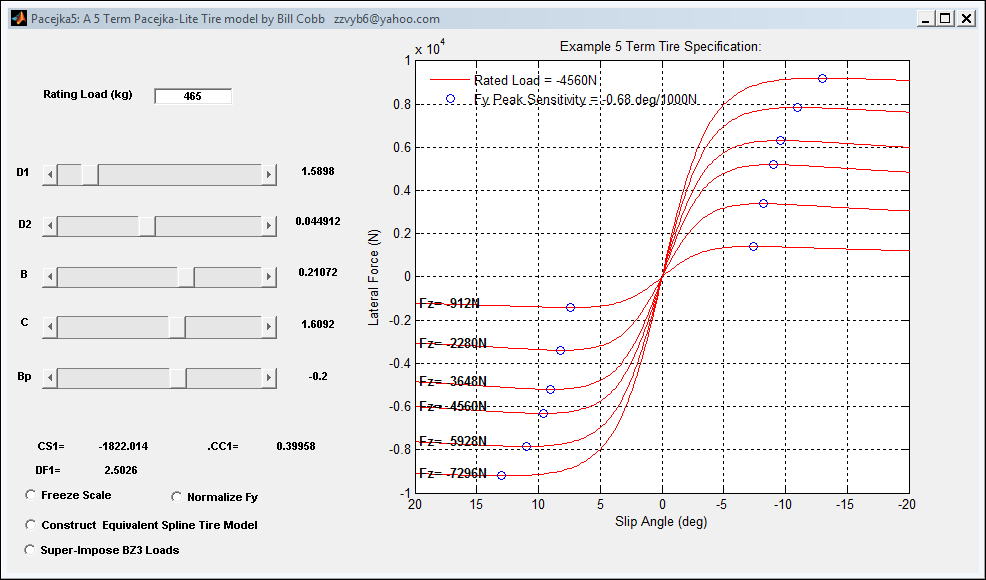
Absolute Lateral Force
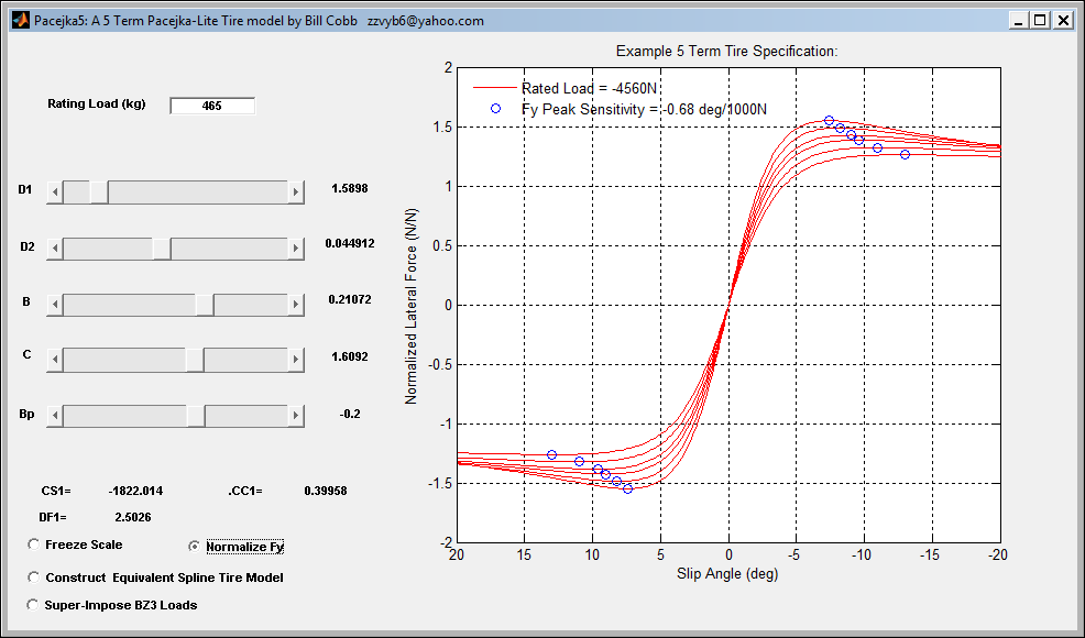
Normalized Lateral Force
No Slip Angle Advance with Load (Analytic models)
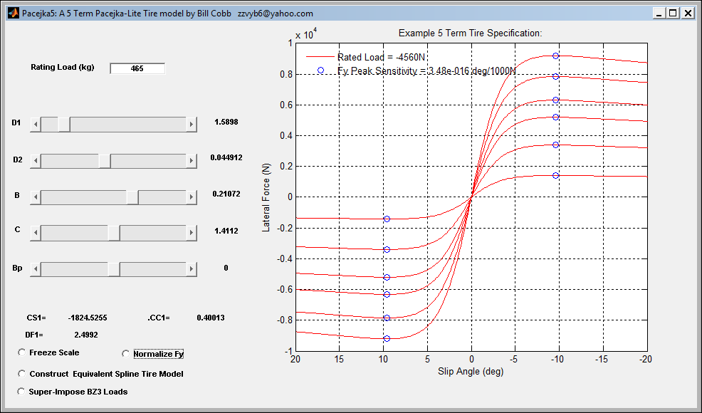
Absolute Lateral Force
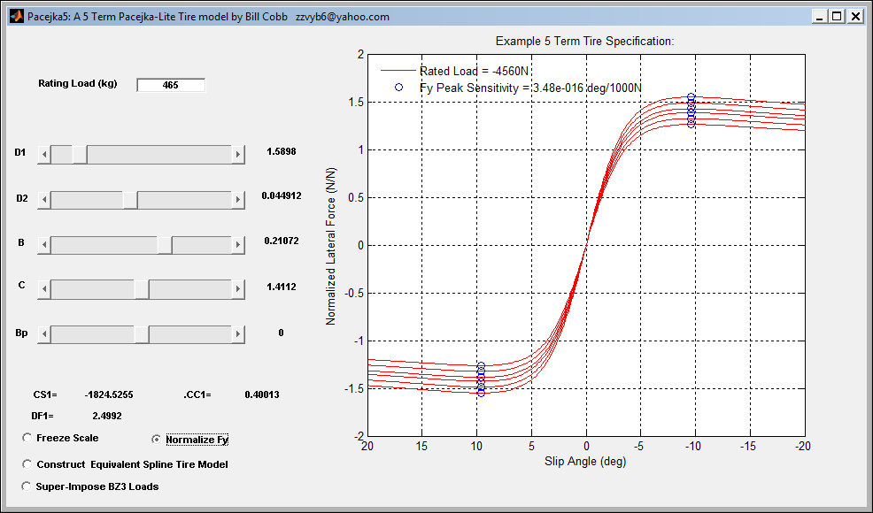
Normalized Lateral Force
Peak Slip Angle Reduction with Load (Camber influence)
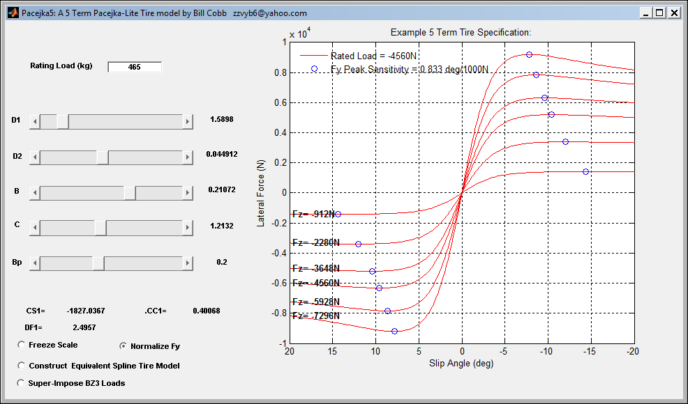
Absolute Lateral Force
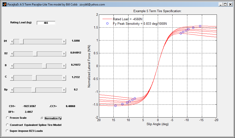
Normalized Lateral Force
Tire Model Fy = f (α, Fz, …)
Re-Sampled & Splined: Continuous & Differentiable Surface
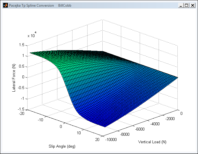
So You want 360 degrees of slip capability? No problem with this technique…
ACKERMANN FUNCTION IN SIMULATION
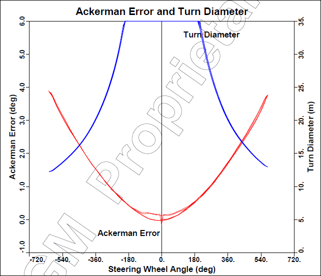
2nd Order Form: Based on Typical Steer Ratio Test Procedure Measurements
Note focus on very small turn radii.
2nd Order: Toe per wheel added to Reference Steer Input f (δ)
δ = SWA/Steer Ratio
Includes Static Toe (if specified)
Positive static toe (inward by convention.
Decrease in Ackermann effect.
Simulation parameter ‘ACKER2’
Adds ‘Toe-Out’
Increases Ackermann Effect.
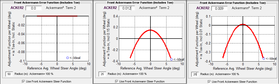
Dilemma:
You should have noticed that there are an infinite combination of static & dynamic toe settings that can accommodate the ‘Ideal’ toe at a single specified turn radius for a given wheelbase. ( 50 m shown )
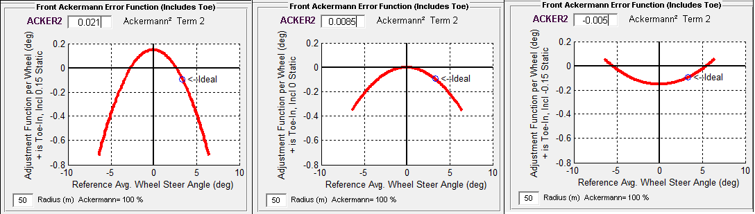
A Unique solution set only occurs when 2 or more Radii are included, as shown
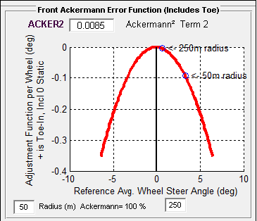
The Unique Solution For this Wheelbase( 25 to 500 m Turn Radius )
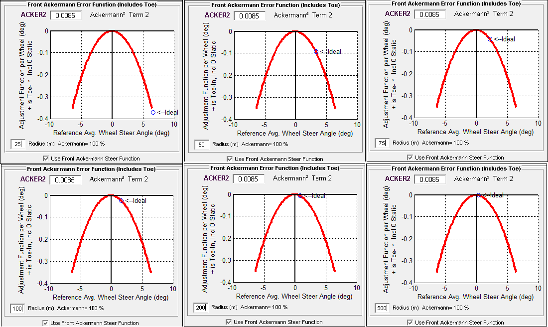
Simulation Ackermann Function
Simulation parameter ‘ACKER2’
Negative value adds ‘Toe-In’
Anti-Ackermann reference
Decreases Ackermann Effect.
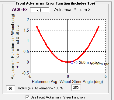
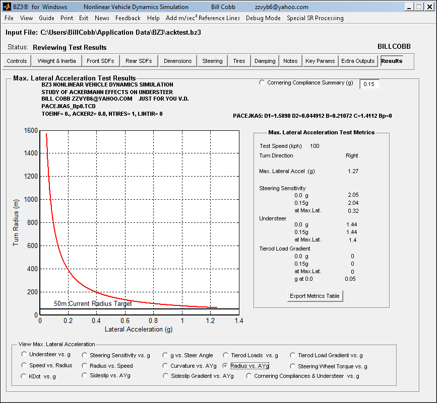
Just in Case You were Wondering… Focus on 50 m Turn Radius because it’s about the Skid Pad size needed for a MaxLat Run Procedure. Racers are keen on MaxLat, right? This a demonstration of Capability, Requirements, and Processing. NOT about Maximizing a Specific Vehicle’s Ability.
Results Methodology
Ramp Steer, Constant Speed test procedure.
Auto-processing for test plots & metrics.
‘All Matlab’ functionality simplifies problem definition & solution
Linear Analysis (Answer Student Questions)
Then Non-linear analysis:
3 Tire types.
Ackermann (Dynamic Toe) via static toe parameter & geometry function.
Effects on:
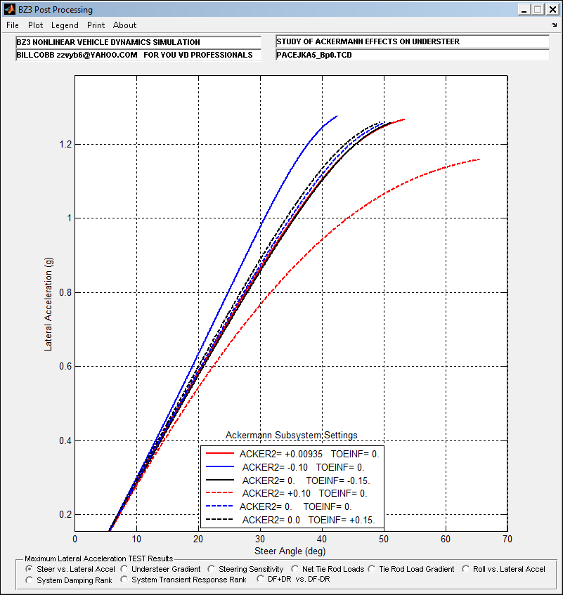
Steering Gain (Ayg vs. Steer)
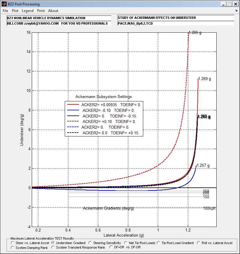
Understeer Gradient = 𝑑𝑆𝑊𝐴𝑆𝑅𝑑𝐴𝑦𝑔 - Ackermann gradient (deg/g)
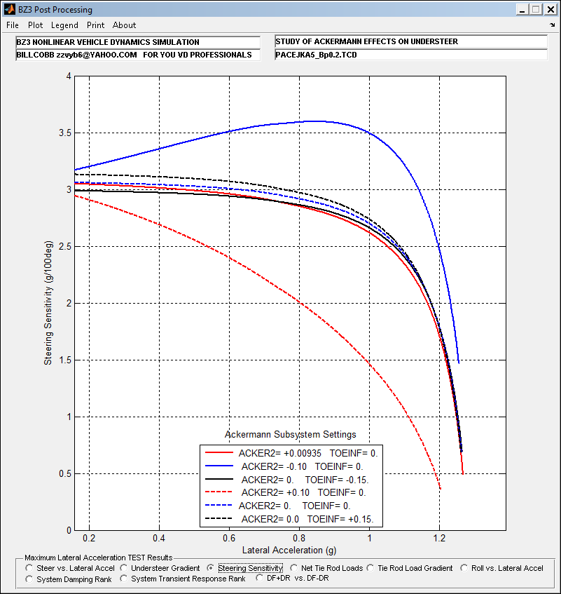
Steering Sensitivity = 100*𝑑𝐴𝑦𝑔𝑑𝑆𝑊𝐴 (g/100 deg SWA @ Speed).
From Experience, a Constant Radius or Ramp Steer test often includes steer inputs greater than the vehicle can respond to (or achieve steady state). So, an arbitrary pre-determined front slip angle gradient limit is chosen based on actual Closed Loop road test procedure results. (Front Cornering Compliance). For this study, a value of 30 deg/g was used. It makes the Metric generation math much easier to accommodate, since the Open Loop limit values can be huge. (Most of the Metrics are derivatives).
Test Conditions
Pro-Ackermann (Reduced outer wheel steer) ACKER2= +
Parallel Steer (Identical front wheel steer angles) ACKER2= 0
Anti-Ackermann (Increased outer wheel steer angle) ACKER2= -
+Static front toe angle (toe-in == anti-Ackermann) TOEINF= +
-Static front toe angle (toe-out == pro-Ackermann) TOEINF= -
Very large Pro-Ackermann function. ACKER2= ++
Very large Anti-Ackermann function. ACKER2= --
Additionally, a range of Ackermann function settings were evaluated using 1 of the tire peak slip location ‘types’.
50m Turn Radius Target Suggested by curvature/radius at Max Lat
( 100 kph Test Speed )
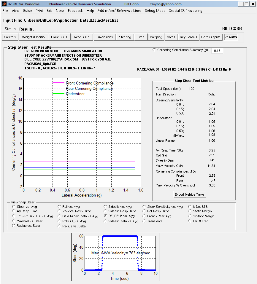
‘Traditional’ Step Steer Validation
Linear Tire, No Ackermann Function. Note that Understeer & Cornering Compliances have the values assigned by the synthesized tire.
Step Tests usually limit achieving consistent MaxLat values because the frequency content can excite instability regions in vehicle response(s) in the non-linear regions. So, I selected the Ramp Steer Procedure:
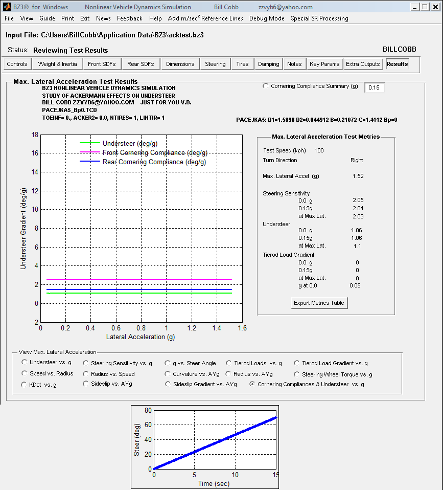
Linear Tire: Added Toe-Out [+ Ackermann]
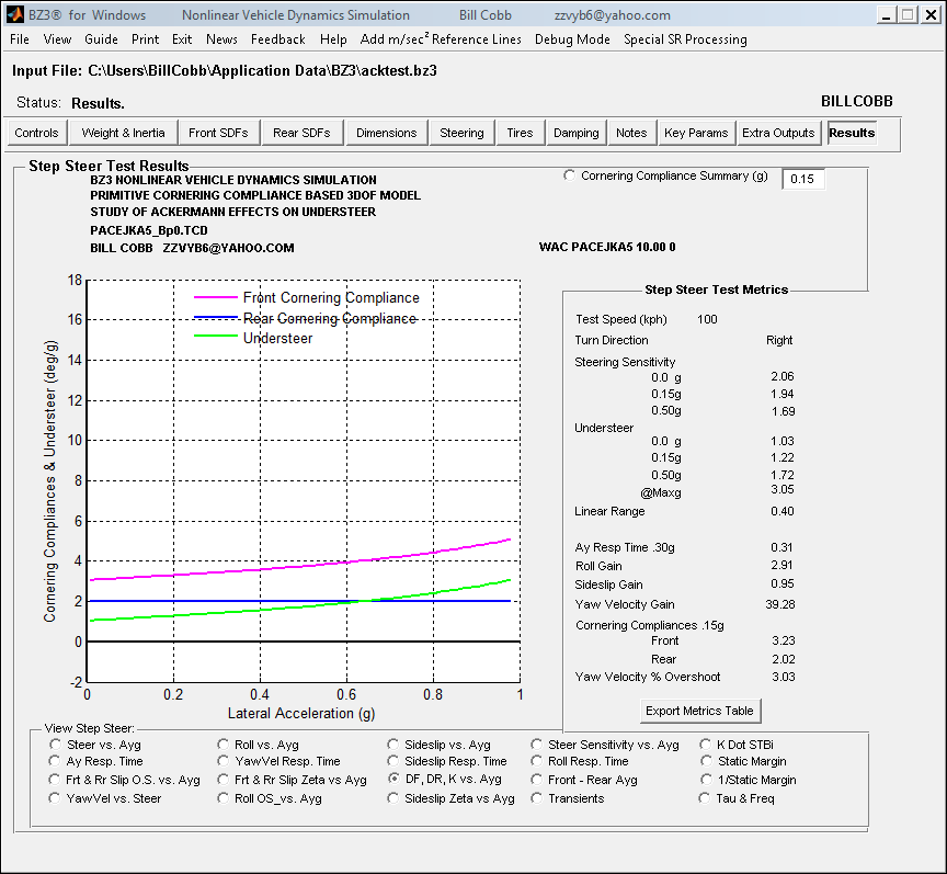
Reduced Outside Tire Steer Adds Understeer
Apparent Front Cornering Compliance Increase: Reduced Front Axle Force Generation.
Rear Cornering Compliance NOT Affected
Steering Gain is Reduced.
Linear Tire: Added Toe-In [- Ackermann]
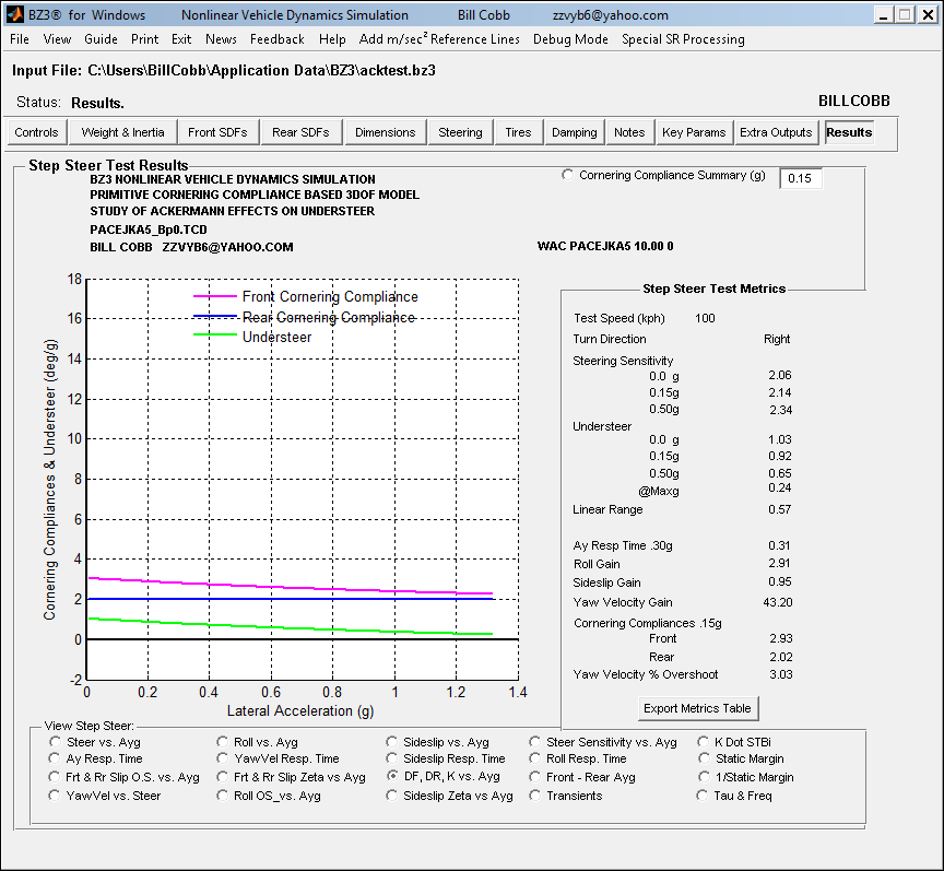
Increased Outside Tire Steer Lowers Understeer
Apparent Front Cornering Compliance Decrease Increased Front Axle Force Generation.
Rear Cornering Compliance NOT Affected
Steering Gain is Increased.
Non-linear Tires Type 1
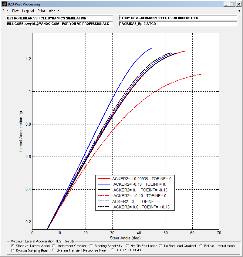
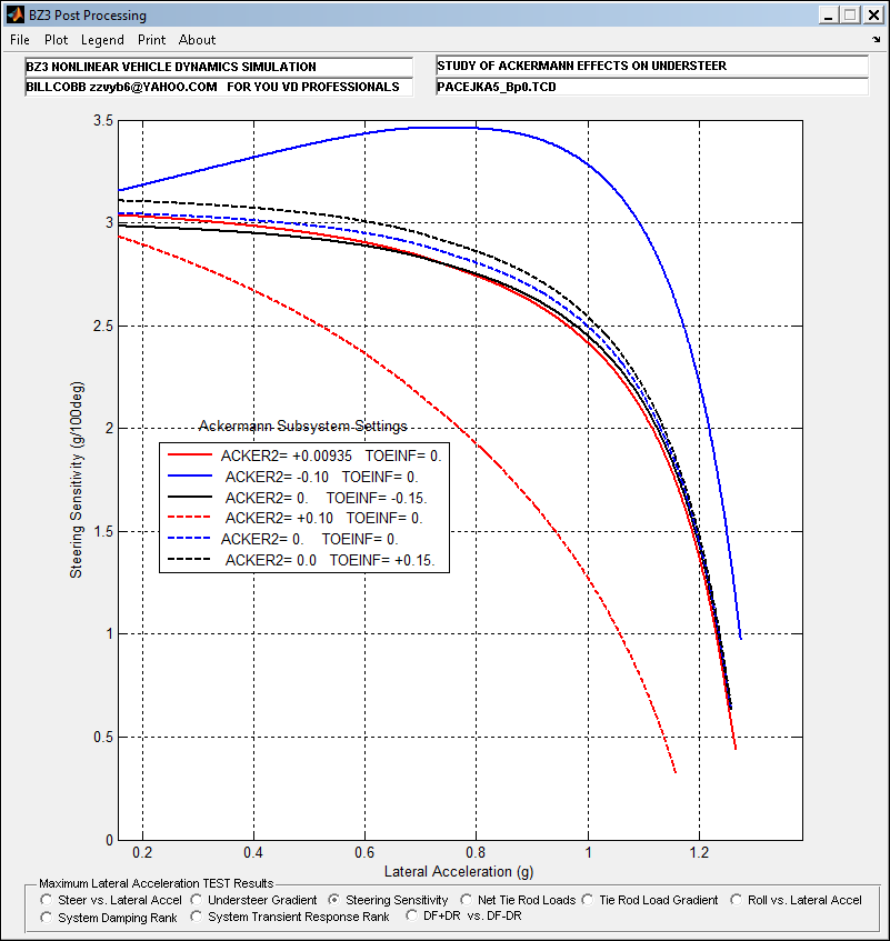
Steering Gain:
Large Pro-Ackermann has largest nonlinearity.
Large Anti-Ackermann has highest MaxLat and best linear gain.
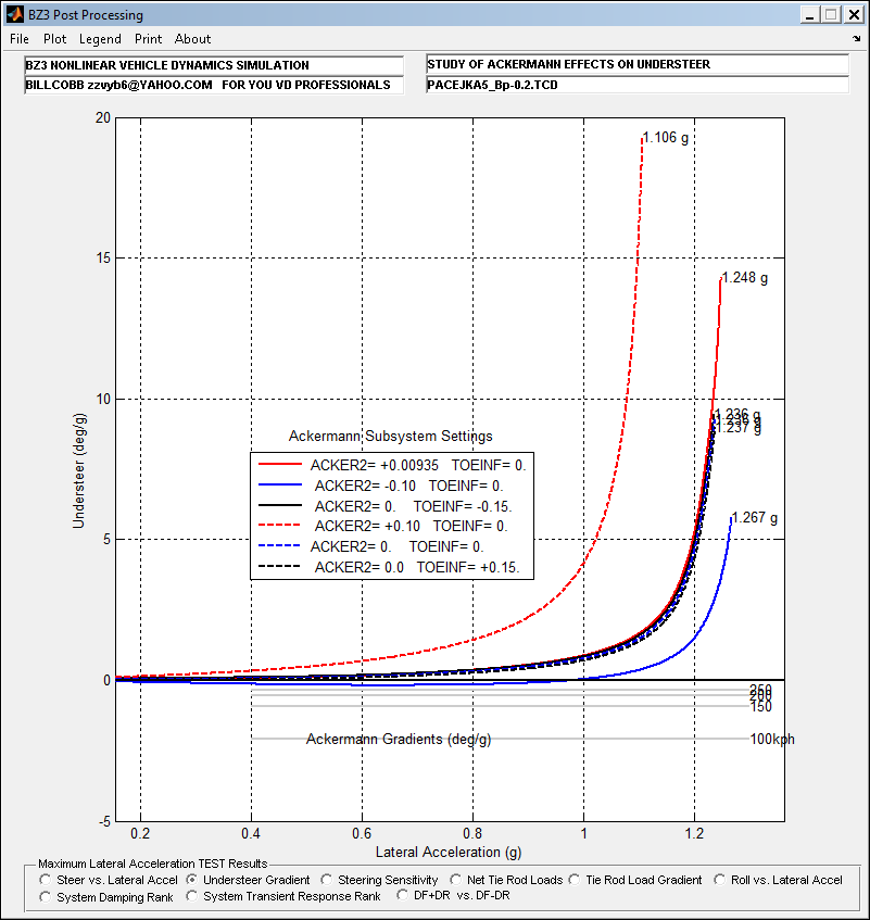
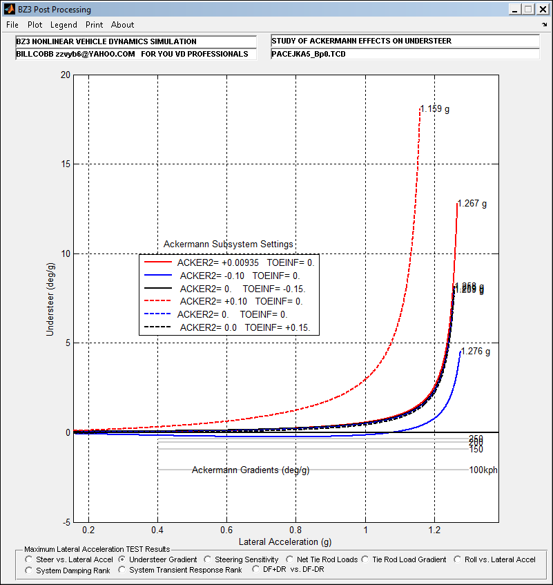
Understeer:
Large Pro-Ackermann has largest nonlinearity range.
Large Anti-Ackermann has highest MaxLat indicated and best linear gain.
Static toe out produced mid-range nonlinear gain and mid-range oversteer.
The amount of oversteer that can be tolerated is described by the ACKERMANN GRADIENT, shown for several speeds.
Speeds above 200 kph may complicate entering high Ayg turns.
I suppose I ought to explain that last comment. Anybody remember this? : (It’s been 30+ years !)

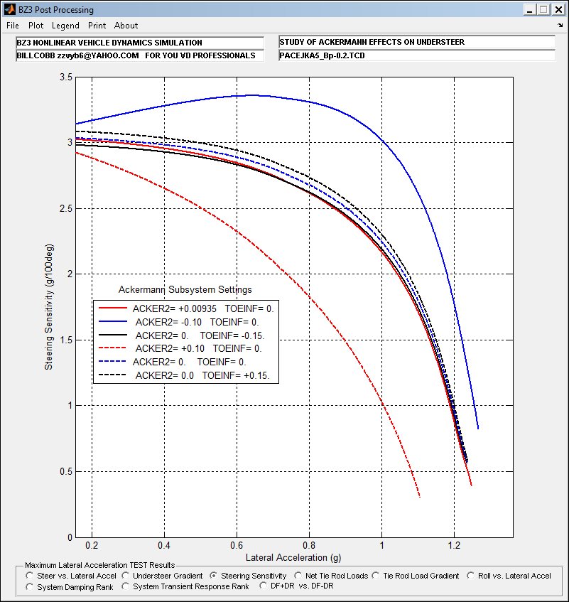
Steering Sensitivity
The initial rising gain is the result of the dip into slight oversteer.
Large Pro-Ackermann has largest nonlinearity.
Large Anti-Ackermann has highest MaxLat and best linear gain range in the region needed to control MaxLat in closed loop (driver) control.
Results: Non-linear Tires Type 2
Results: Non-linear Tires Type 3
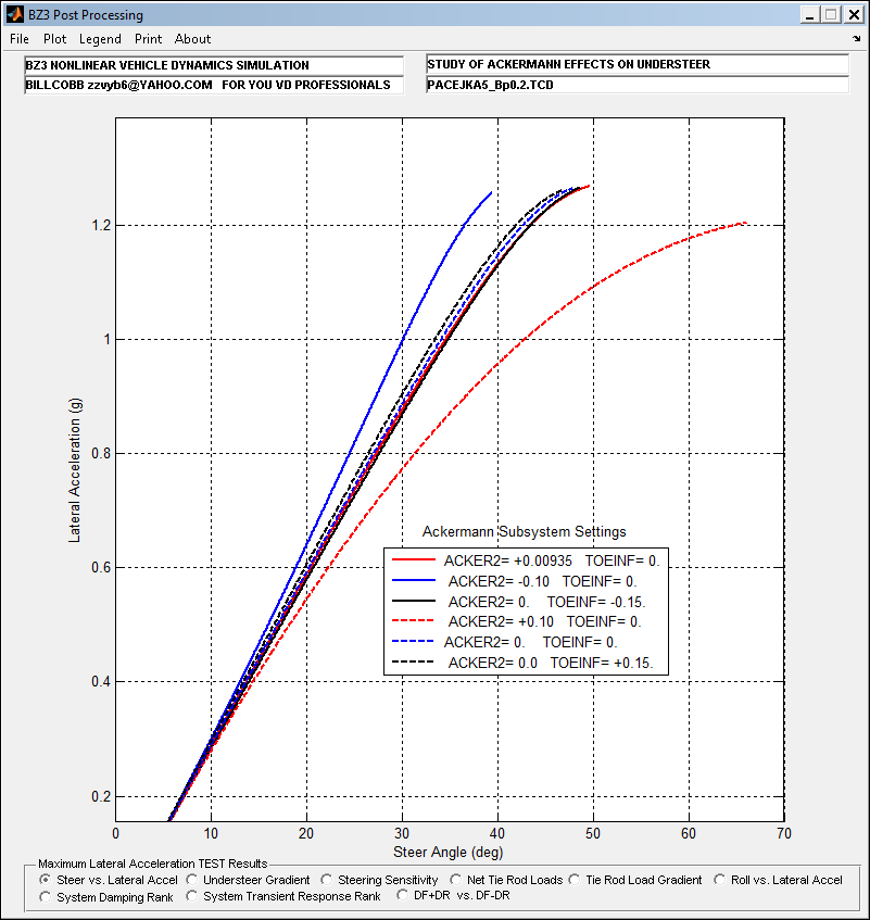
Results:Non-linear Tire Types
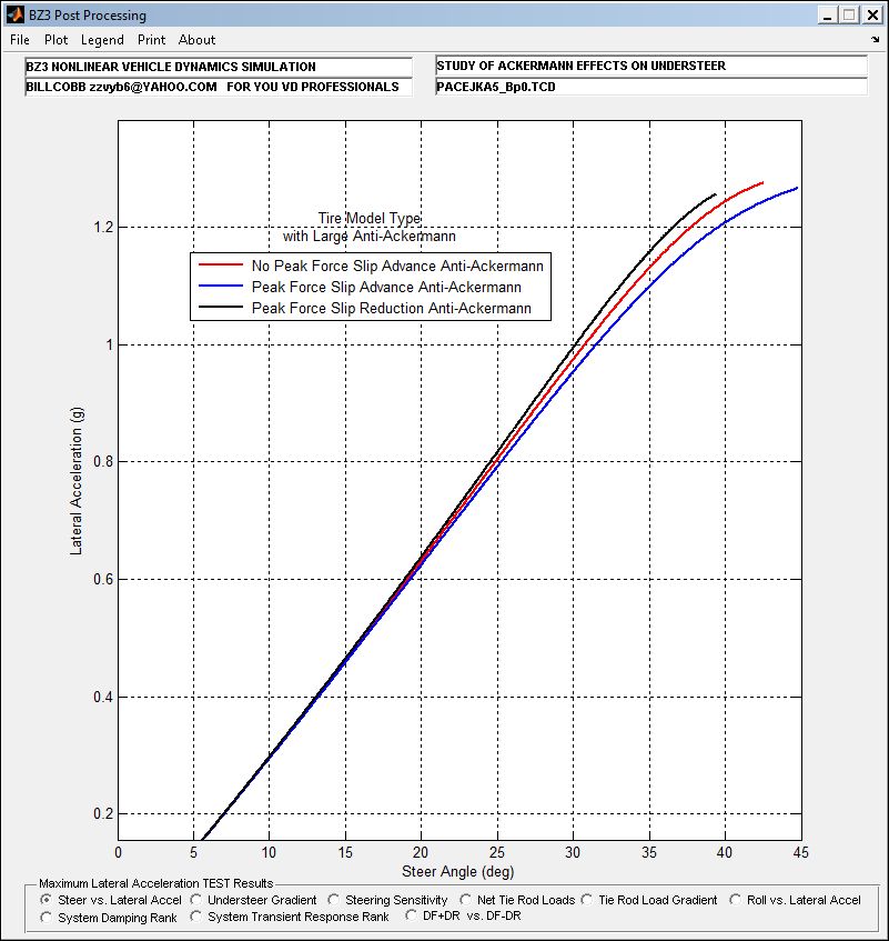
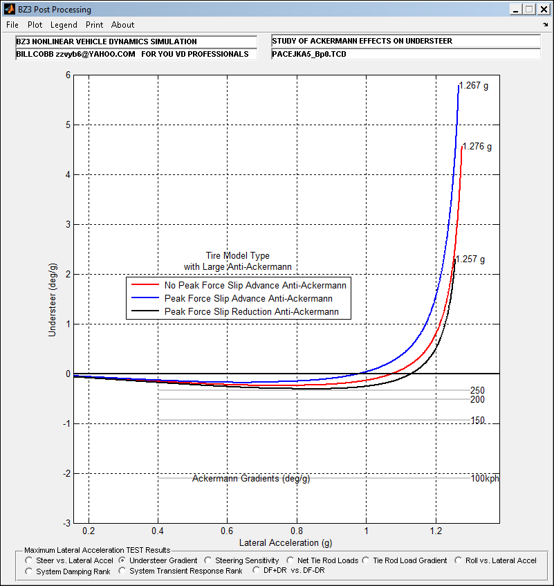
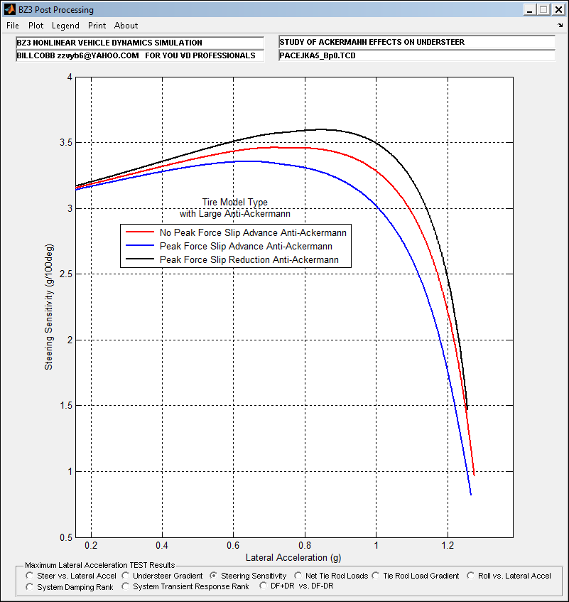
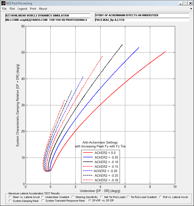
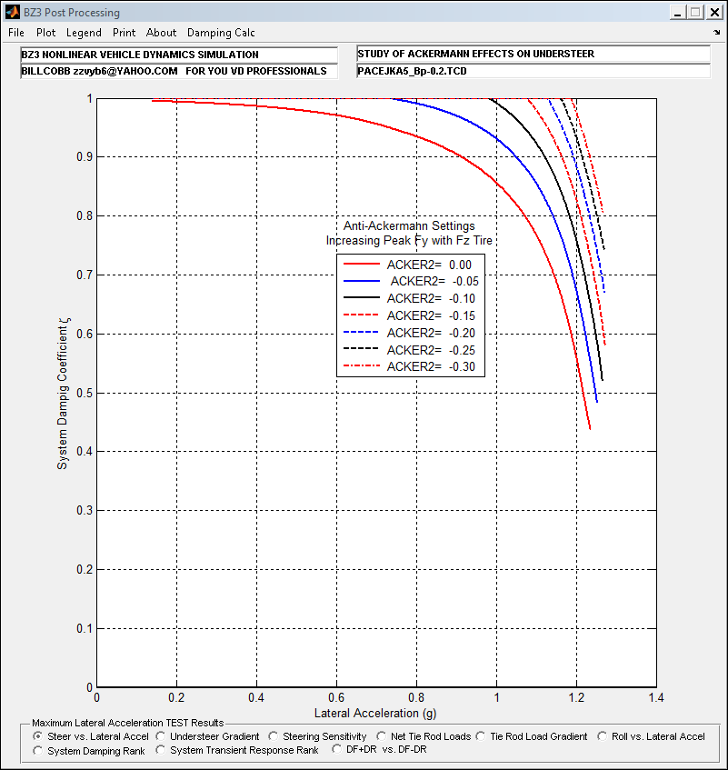
Large Anti-Ackermann can show an effect. What does a sweep of values reveal?
Effect(s) on Lateral Acceleration Gain
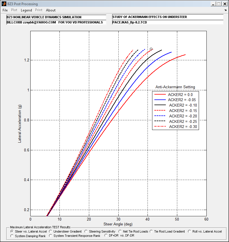
-0.162 for ACKER2 @ peak Ayg Suggests an Optimization Challenge!
Effects of Ackermann Sweep on Understeer
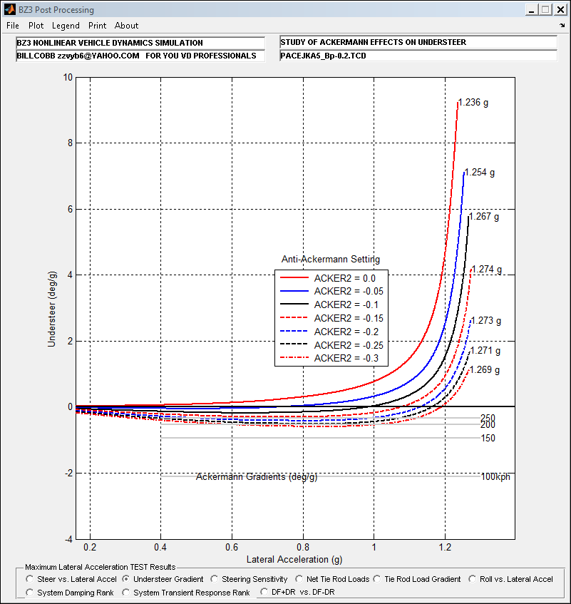
Max Ayg determined at the 30 deg/g Front Cornering Compliance break point.
Ackermann gradients at a few speeds of interest, including the one used in this study.
Effect(s) on Steering Sensitivity
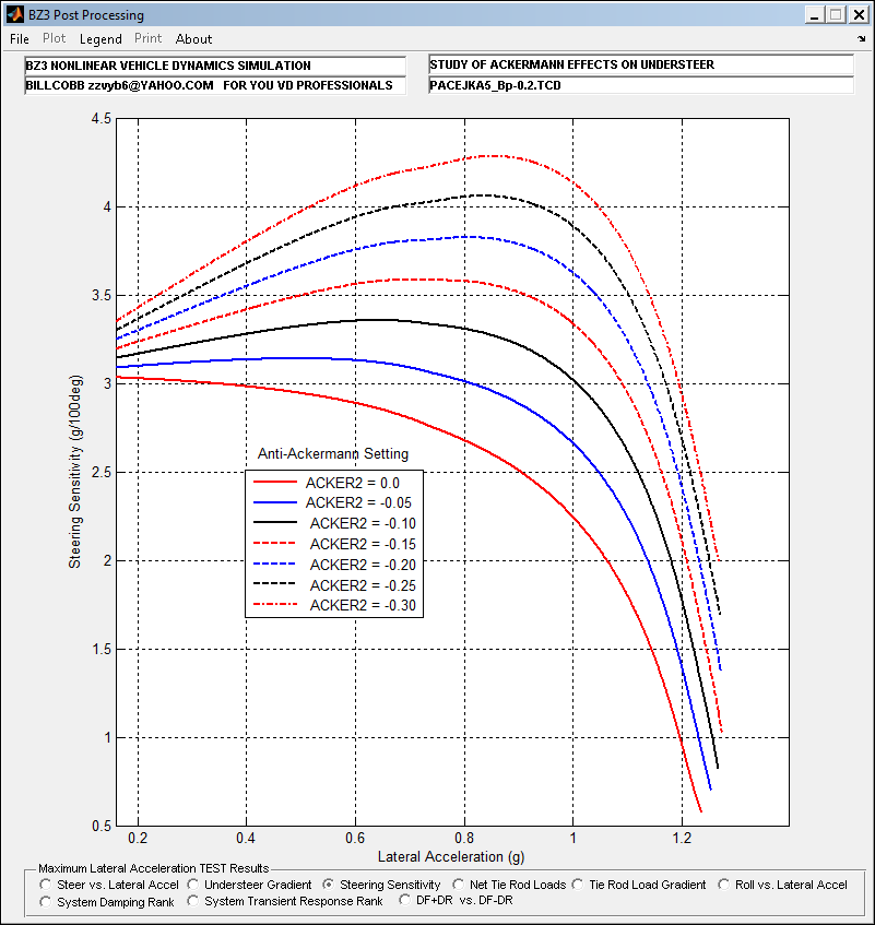
This amounts to about 2.75 deg of toe-in for the 50m turn radius at MaxLat.
Conclusions
Ackermann steering specifications ought to recognize multiple turn radii constraints. For racing, track radii need to be known.
Ackermann steering geometry influences intended to address turn radii conflicts because of vehicle width has only minor effects on Handling characteristics. May not be large enough to measure in normal driving situations.
‘Dynamic Toe Change’ resulting from wheels being steered can have a MAJOR influence on Handling when progressive toe-in (Anti-Ackermann) settings amount to several degrees of difference, especially when peak Fy slip angles advance with Fz. BTW: this ‘car’ had a front biased TLLTD which ‘works’ the outside tires producing less limit understeer.
Too much of a Dynamic Toe recipe may introduce oversteering regions, making even closed loop (driver) control impossible.
Transient response behavior is also affected, but I’ll let you keep guessing what and how much because local deer are destroying my fences. Hint: DF-DR is understeer. DF+DR is ‘yaw dampin’ as Bill Milliken would say it…