
Keep these resources open during your team’s entire frame design process:
2027 FSAE Rulebook
2027 FSAE Structural Equivalency Spreadsheet (SES)
2026 FSAE Tech Inspection sheet
2027 suspension subteam geometry and loads
2027 ergo subteam packaging
2027 drivetrain subteam packaging
The Guide To 2026 Frame Rule Changes has details about even more rules. (Though some obviously change year to year.)
You can get a great start on the 2027 SES before it is released by filling out the 2026 SES. Almost everything will carry directly over.
Submit 24 hours and one second late for ESF, SES, Design, Cost, or Presentation and you will lose your registration. Submit a week early, don't get burned.
Notice of future rules Development
A rules package is in development for 2028 around better implementation of driver harness attachments. We expect this to be the most significant chassis rules change since the addition of the EV requirements in 2013, or the addition of the FBHS in 2009.
1. Mount lap and anti-sub belts below the seat bottom.
We will begin enforcement for 2027. Do not mount to the SIS diagonal, use the lower SIS or a cross-car structure. If the anti-submarine belts go down under the driver's leg and then back up to the attachment, that extra down length will simply become slack until the belt is tensioned in the loading direction. Small dips of ~25mm may not be too problematic, but 50-75mm is too much. It's about the tangent of the downward angle in the section of the anti-sub belt from the attachment to the point of driver contact.
The angle in T.2.7.2 really only works for conventional saloon car seats, which are almost never seen in FSAE. The forces in a reclined position are forward, not upward. Anti-sub attachments need to be at or rearward of the harness buckle.
See the Formula position on page 11 of the Schroth manual.
This should be an easy enough rules change.
2. Increase cross-car tubes for harnesses to Size A.
This should also be an easy enough rules change. The test loads for lap and anti-submarine belts are the same as for shoulder harnesses. So the stresses and bending on the tubes are the same. So the tube size should be the same. We will also need to evaluate overall monocoque floor requirements
3. Lap Belt Mounting Width
Once the cross car tube strength is increased, it is likely that many more lap attachments also belong on cross-car tubes. Some cars are wider than 600mm, and this leaves the sides of the lap belt at more than 45deg angles. The width of lap belt attachment points should match the width of drivers hip bones, approximately 400mm. Higher side attachment, decreases body contact, and increases the tension in the belt for the same load.
Additionally, the minimum length of a buckled and tightened lapbelt is about 550-575mm, hole to hole. Raising the lapbelt mounting holes up will likely prevent smaller drivers from actually tightening the belts.
We'll have to look at chamfered or narrow monocoques to evaluate the suitability of mounts wider than the flat floor.
Again this will not be a particularly complex rule change.
4. Harness Loads At Triangulated Nodes
Cross car tubes for Anti-Submarine and Shoulder belts should be at triangulated load paths to react the longitudinal and vertical loads. Lap and Anti-Submarine attachments on the Lower SIS should be near a triangulated node. This is a more significant geometry change. Teams will adjust SIS diagonals and the bottoms of MH depending on harness attachment location.
This is likely to include the SH tubes. The Longitudinal Shoulder Harness Brace will represent a whole new required tube.
None of this is complicated, but these will be new and different requirements.
2027 Rules affecting All Teams
F.3.4.3 Fully Weld Welded Inserts
Welded inserts for regulated attachments must be welded on both ends. An insert placed through and welded to only one side of a tube is not acceptable.
F.3.4.4 Reminder Not To Grind Welds
Do not grind welds. The cross section of the weld bead is structure we're counting on. If you have to do a little spot grind to clearance one ugly bump, that's reasonable. But grinding welds flush is prohibited, especially in anything regulated by structural rules. When welding inserts, for example, the insert should be proud of the tube surface by about a wall or weld thickness so there is a good bead.
F.5.6.6 Template Neck Thickness
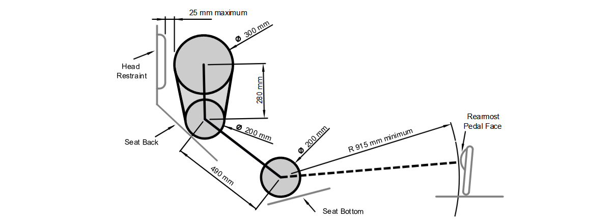
Percy will have a neck - tangent to the shoulder circle and the helmet circle. Two issues are being addressed. 1. SH bar under helmet rim, extremely bad. 2. SH bars too close to drivers, belt hardware digging into drivers instead of just belt webbing. Expect further rules development to push the SH well behind the seatback in 2028. The spacing is defined by the requirement for 3-bar adjuster clearance. 2-bar adjusters for 3in Shoulder Belts are very expensive.
F.5.9.6, F.6.3.6 V-FHB, X-FHB and X-MHB are Banned
Crossed-X Main Hoop Braces and Front Hoop Braces are now officially prohibited. We thought we'd gotten rid of this long ago. The nature of an X-configuration puts the brace in bending, so we're using the requirement for straight braces to also require them to be uninterrupted.
V-shaped Main Hoop Braces meeting at the top of the MH are acceptable. Some design judges prefer that approach.
V-shaped Front Hoop Braces are not acceptable, they point at the driver.
T.1.8.3.b Aluminum firewall for lithium batteries and packs
Your Low Voltage Lithium chemistry battery needs an aluminum firewall.
T.2.4.1 Harness Attachments Go on the inside of the chassis, on the bottom tubes.
The harness attachments cannot be on the outside of the chassis. We will start enforcing lap and anti-sub attachments on the floor tubes of the chassis only, not on SIS diagonals.
T.2.4.3.d Do Not Put Harness Tabs In Bending
Lap and anti-sub belts sharing the same attachment is discouraged, because it is difficult to get both belts aligned properly. Once you understand that the loading on the lap belt should be essentially vertical and forward, and the loading on the anti-submarine belt should be essentially horizontal and forward, you can see that the attachments need to be basically perpendicular. Do not bend your own harness ends.
It is not possible to have a lap and anti-sub belt aligned when both are clipped on a single eyelet. An eye can be positioned vertically in a tube, not necessarily angled. An eye is required for each clip end. Eyes within 125mm can share the same monocoque insert, and might as well because the test load is doubled when spacing is <=125mm.
Or the anti-sub can go around the eye shank, while the lap belt clips to the eye.
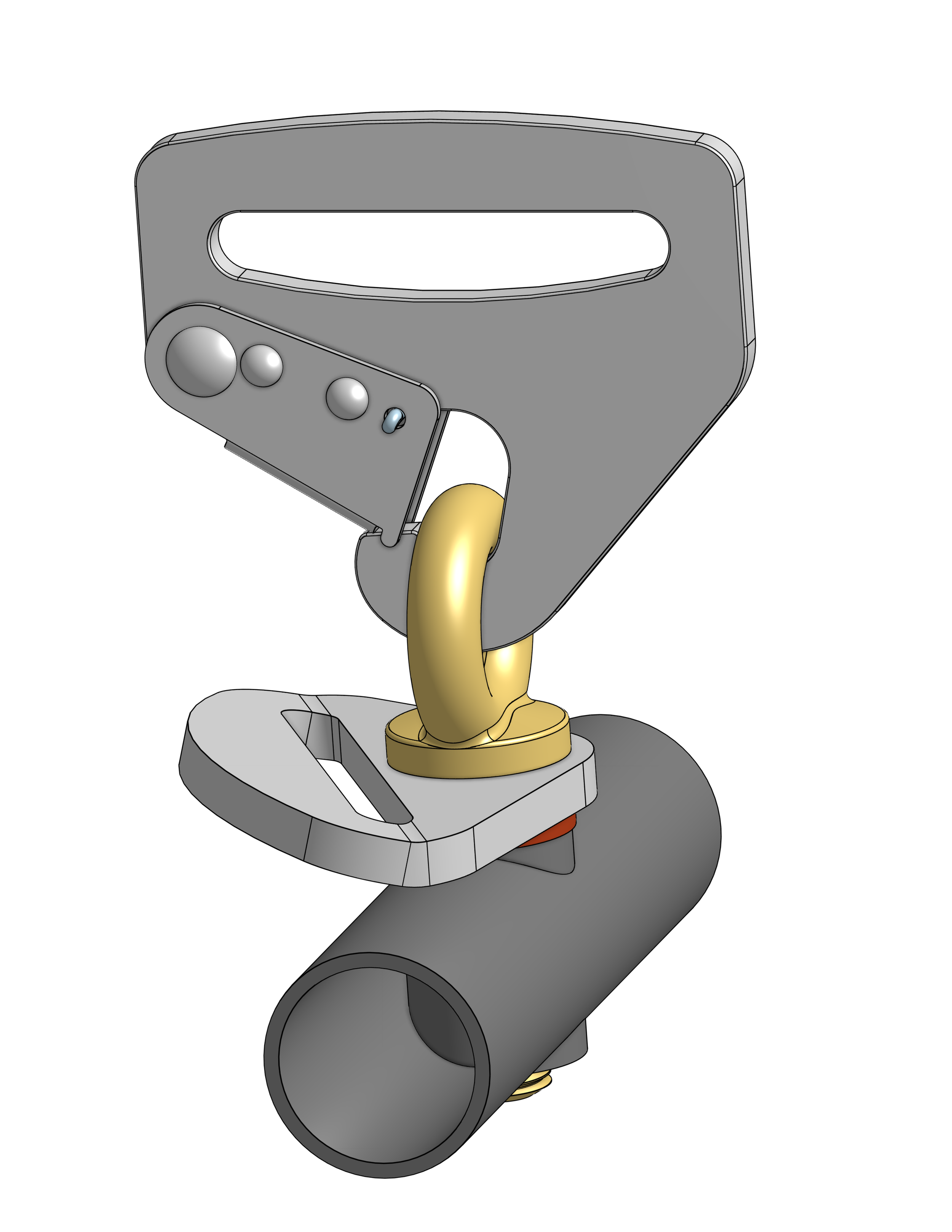
As with any bolted harness end, there is a sleeve around the eyebolt shank that gets clamped and allows the belt to rotate.
T.2.7.4.c Wrapped Anti-Sub Reminder
There must be a continuous floor between all belts and the ground.
T.2.8.3 Head Restraint Aero
Fairings that remain inside the rollover envelope will be considered part of the head restraint. Fairings that stick outside the rollover envelope are strictly prohibited.
T.2.8.5 Head Restraint must be mounted top and bottom to the chassis
Last year, we thought the worst-case test load would get teams to stop using a single twig to mount the head restraints. Walking through the garage, most of the teams understood the assignment, and all the designs where the head restraint was mounted to the chassis top and bottom looked sensible.
Note: Beams attached to the rear of the head restraint (designed for fore-aft adjustment) are not acceptable. These represent loadpaths directly into the driver's helmet in a rollover. Use different thickness padding or spacers instead.
T.6.1.7, T.6.1.9 Compressed Cylinder Safety
Good engineering practice: A non-adjustable pressure relief valve must limit the maximum operating pressure. The pressure relief must be lower than the tank rating. The driver must be shielded from any pressurized cylinder and its pressure relief valve by a steel or aluminum firewall >=1mm.
One team did such a good job packaging transverse air cylinders under the drivers legs that we agreed to consider approving that location in Tech Inspection. This option will be available to all teams in 2027. The rules have been modified to prohibit cylinders alongside the driver in side view. There needs to be a sturdy firewall above for drivers jumping in and out of the car, with 25mm clearance between the cylinder and the firewall to allow deflection without contact. And grommets for the lines passing through the firewall.
2027 Rules affecting Tube Teams
F.6.6.3 MHB Miter
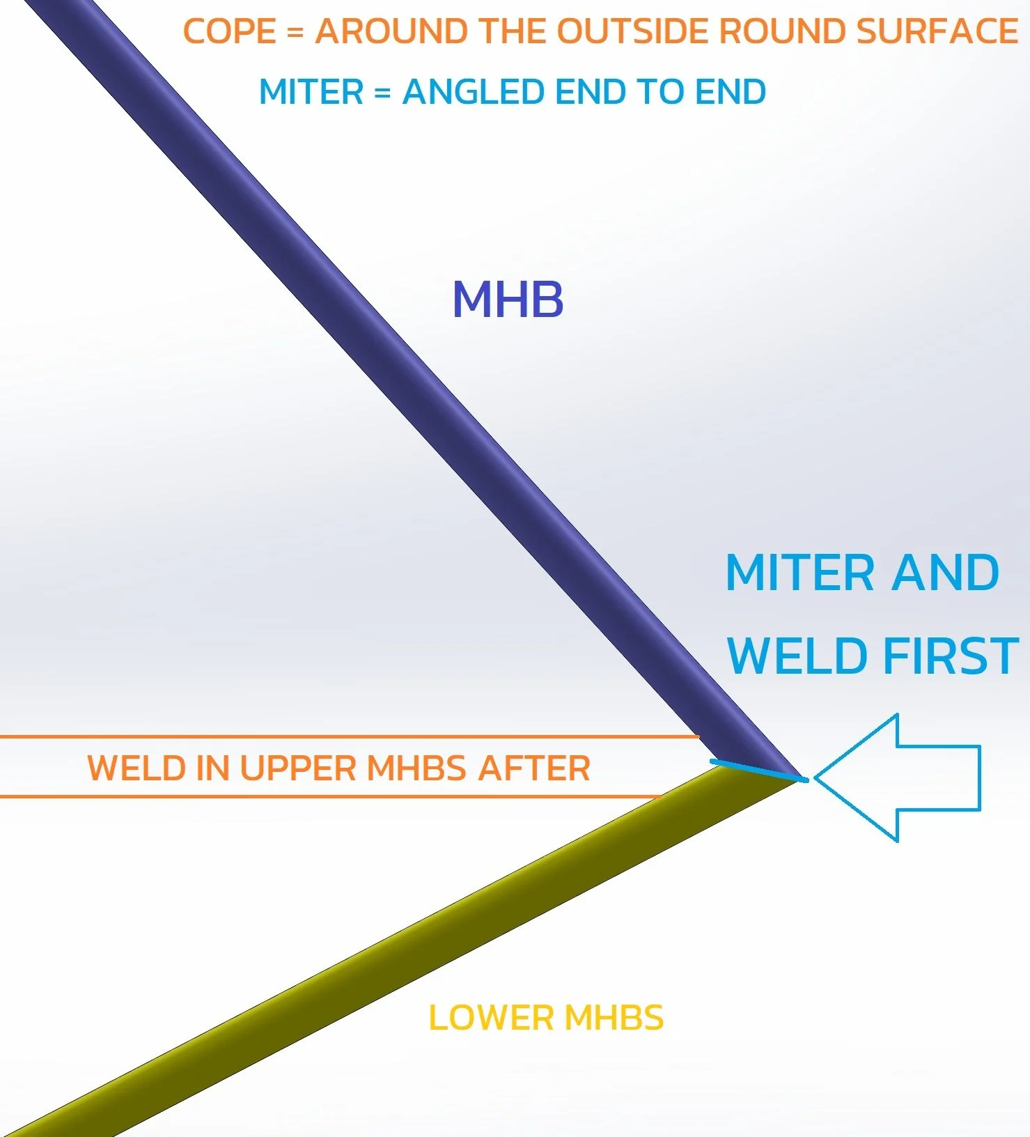
The lower ends of the MHB must be mitered to the Lower MHBS for a continuous load path. If the SH forms part of the MHBS, the MHB/MHBS miter must use a larger diameter to go around the SH. If forward MHBs are used, and the diagonal SIS is the start of the Lower MHBS, the miter must interrupt the Upper SIS. If the interrupted SIS is still straight, it does not have to be increased to Size D.
T.2.5.1, T.2.7.1-2 Harness Attachments Go On Floor Tubes
Proper harness location means the attachments need to go on the floor tubes. Not the diagonal SIS.
15 Sep 2026
Reminder per F.8.6.3 that pedal assemblies need 25mm clearance to the Front Bulkhead, Diagonal, and AIP.
Do not mount pedals and pedal rails to the lower Front Bulkhead tube.
2027 Rules affecting EV Teams
F.10.1.6 Pop Rivets should not be used in Tractive Battery
Even closed end pop rivets, the other end is open and might introduce metallic debris. We're not in a position to properly inspect their usage. Only solid rivets will be permitted in the Tractive Battery by 2028.
F.10.2.3 Fully Enclosed Modules
Internal walls must extend to an internal or external lid above any module. Internal and external lids must be mechanically attached, and must meet F.10.2.2 wall material requirements. The lid on top of modules does not count as mechanical attachment for the modules.
F.10.2.5 Walls And Floors Reminder
This has been the rule since the first EV competition. Every external and internal wall must directly attach to the floor. Not to another wall, and maybe that wall is attached to the floor. Every external and internal wall must be structurally attached to every other wall it reaches. Fastener spacing must be frequent enough to maintain > 135N / mm of length.
Shear and peel values or test results are required for bonded joints. Both walls need a flange, to keep one bond in shear and avoid the peel requirement. Bonding on edge is not appropriate for SES calculations. If you try that, we will make you test a sample to > 135N / mm of length.
F.10.3.2 Modules Must Be Mechanically Attached To Containers
Attachments must show they can support the SES acceleration loads in the direction of removal. A lid above the modules does not count as mechanical attachment.
F.10.3.5 Module Structure Testing
Instead of the SES column equivalence, we agree with the team that suggested physical testing of a spare module structure with no cells. Get the SES test loads based on your battery layout. Manufacture a spare. Heat it up >=60C during the test. Load it one direction at a time in X,Y,Z >= your test load. No permanent deflection or cracking permitted. We'll see how this goes as an option. We would like to see this become the standard.
F.10.5.2 Clarification Appropriate Tubes For Mounts
All attachment points for the tractive battery must attach to a Size B tube between two triangulated nodes. Tubes straight or angled across the car between nodes on either side qualify. The intent is to prohibit battery mounts to tubes that are not integrated into the main load paths of the chassis. The intent is for chassis design to get the main rules load paths and maybe some cross tubes close to where the battery mounts will be, then use battery and chassis mount design to span the shortest remaining distances from the chassis to the battery.
F.10.5.8.e Reminder No Mounts On Open Volumes
Except for container wall thickness, each Tractive Battery Container mount must have no gap to module structure.
F.11.1.3 Motor And Controller Mounts
Especially when they're next to the driver, motors and motor controllers need sturdy mounts proportional to Tractive Battery Mounts. In lieu of test load for motors and motor controller mounts, let's start by making sure all motors and motor controllers are mounted below the height of the SH.
T.1.6.3 Clarification
For thermal protection for the driver, the entire tractive system, not just the battery, is considered a heat source.
2027 Rules affecting Mono Teams
As always, if you are stuck with old molds that are out of compliance new rules, get in touch so we can work out a plan.
Look for new math in the SES addressing very skinny monocoque MHBS load paths.
F.4.2.3.d Rig Stiffness
The derived modulus from the tube test, as calculated by the SES, should be >=85%. We've wanted a limit here for a long time. This will increase to must in 2028.
F.4.3.1 No Unidirectional next to core
Unidirectional plies must be enclosed by balanced plies. Unidirectional plies must not be the nearest plies to core material. This is now a hard rule.
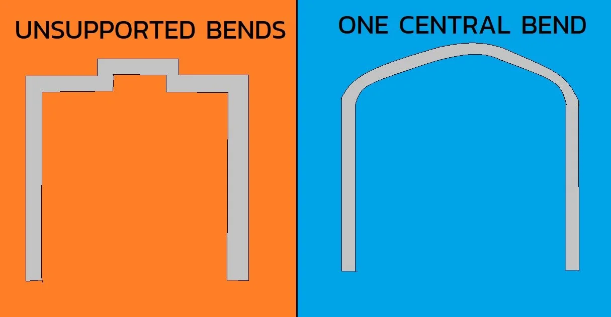
F.5.7.8 Square Wave FH
The outer perimeter of the Front Hoop should not have concave sections across the top.
F.7.4.3.d FH Lamination Reminder
The skin entered into the SES for FH lamination is the one that runs from the outer skin, around the FH, and back to the outer skin.

T.2.5.1, T.2.7.1-2 Harness Attachments Go On Floor Tubes
Proper harness location means the attachment location needs to be carefully considered. Attachment of the anti-sub to the SIS vertical is almost certainly not appropriate.
F.7.8.1 MH Attachment Clarification
We are looking for MH mounts to be basically at the bottom and basically at the top of the monocoque. Not elevated above a big corner chamfer so the bottom mount is in the middle of the monocoque. Not just at the top of the SIS so the top mount is in the middle of the monocoque. We're looking for spacing as wide as practical between the top and bottom mounts to react moments.
F.7.8.6 Attachment Good Engineering Practice
Mounting and backing plates must be near circular or near oval. Straight sections are fine. Concave sections are not. No cutouts except for bolt holes.
This applies to all attachments with an SES test load.
F.7.9 Shoulder Belt Good Engineering Practice
Tested custom webbing brackets need to approximate a tube wrap:
straight, round cylindrical section
perpendicular to webbing
minimum 7/16" diameter